Vessel filter

Inactive Publication Date: 2010-08-03
AMRIS PATENTE VERW
View PDF17 Cites 47 Cited by
  • Summary
  • Abstract
  • Description
  • Claims
  • Application Information

AI Technical Summary

Benefits of technology

[0065]FIG. 3e shows another alternative cutting pattern with additio

Problems solved by technology

Depiction and position determination of a vessel filter in an MR imaging system, however, is difficult.
Metal vessel filters are only visible as an artifact, and vessel filters made of pl

Method used


Image

  • Vessel filter
  • Vessel filter
  • Vessel filter

Examples


Embodiment Construction

[0083]For the purposes of promoting an understanding of the principles of the invention, reference will now be made to the embodiments illustrated in the drawings and specific language will be used to describe the same. It will nevertheless be understood that no limitation of the scope of the invention is thereby intended, such alterations and further modifications in the illustrated device, and such further applications of the principles of the invention as illustrated therein being contemplated as would normally occur to one skilled in the art to which the invention relates.

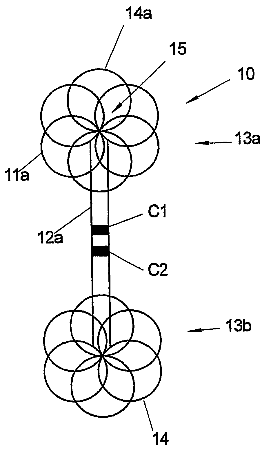
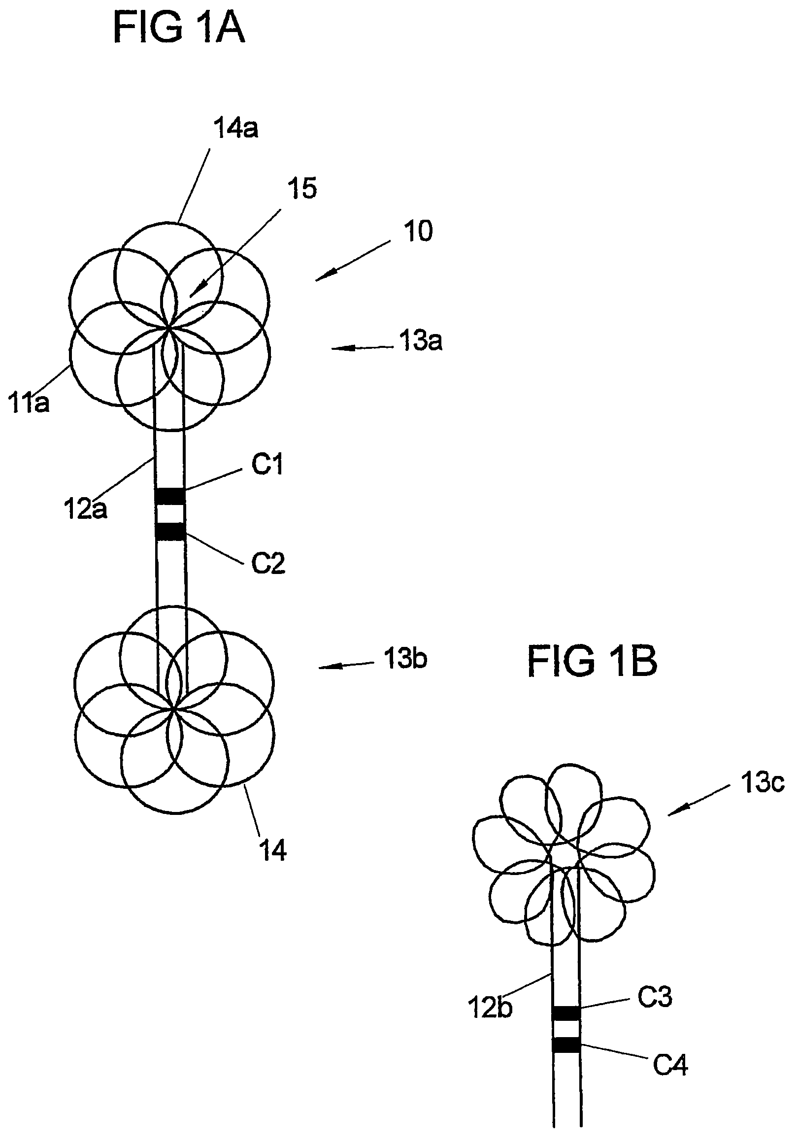
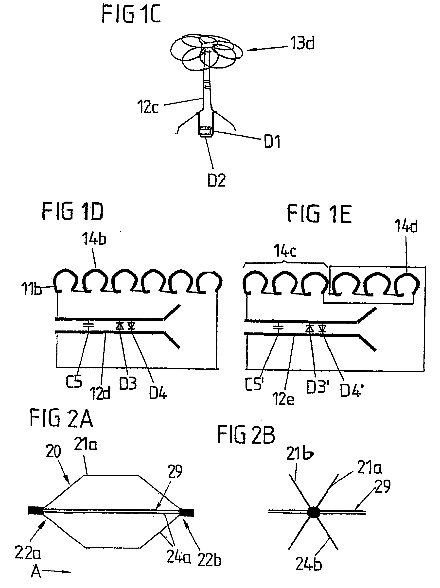
[0084]In FIGS. 1a-1e, vessel filters are shown in the variant of a so-called umbrella filter. The umbrella filter 10 in FIG. 1a is designed as a double-filter in which a conductor loop 11a forms an elongated base 12a and, on both long sides, base 12a is guided, so that two filter cages 13a, 13b are formed, each of which consists of a number of conductor loop windings 14, 14a arranged in a circle. At the center ...


PUM


Abstract

The invention relates to a vessel filter comprising at least one conductor loop (21) which forms the inductance of an electric resonance circuit. According to the invention, the conductor loop (21) forms the vessel filter or parts of a vessel filter. The invention provides a vessel filter which is characterized by good mechanical properties, especially a high degree of flexibility and stability, offering good representability in MR imaging systems.

Description

CROSS-REFERENCES TO RELATED APPLICATIONS[0001]This application is a National Stage of International Application PCT / DE2003 / 004199, filed Dec. 12, 2003. Applicant claims foreign priority to benefits under 35 U.S.C. 119(a)-(d) of the following foreign application for patent: German Application No. 102 58.708.6, filed Dec. 12, 2002, which is hereby incorporated by reference in its entirety.BACKGROUND OF THE INVENTION[0002]The invention concerns a vessel filter that includes a conductor loop that forms the inductance of an electrical resonance circuit.[0003]Vessel filters are structures that are inserted into traversed veins and arteries of the human or animal body, especially the inferior vena cava, in order to prevent penetration of blood clots or sclerotic vascular material into organs of the body, especially the lungs and brain.[0004]For application, vessel filters are generally mounted or fastened in the unexpanded state on a wire to be introduced to the body or brought to the targ...

Claims


Application Information

Patent Timeline
IPC IPC(8): A61M29/00A61B5/05A61F2/01G01R33/28G01R33/34
CPCA61F2/01G01R33/286G01R33/34084A61F2002/016A61F2230/005A61F2230/0078A61F2230/008A61F2/0105A61F2/0108
Inventor MELZER, ANDREASSCHAEFERS, GREGOR
Owner AMRIS PATENTE VERW
Why Eureka
Try Eureka