
Environmental air control system

Inactive Publication Date: 2010-08-10
DC & BV FRANCE HLDG
View PDF25 Cites 43 Cited by
  • Summary
  • Abstract
  • Description
  • Claims
  • Application Information

AI Technical Summary

Benefits of technology

[0009]FIG. 2 is a three-dimensional drawing of the environmental air control system of the invention showing the modifications for either an air conditioning or heat pump system and the additional requirements for the installation of either type system;
[0010]FIG. 3 is a schematic drawing of the environmental air control air conditioning system of the invention in the cooling mode of operation;
[0011]FIG. 4 is a schematic drawing of the environmental air control air conditioning system

Problems solved by technology

Many of these depended on reheating the cooled air either by use of additional heat from the oil or gas furnace or electric heat, both of which are cost prohibitive.
Other approaches have included multiple evaporators and condensers but these were often difficult to control and required complex controls both for the temperature and the storage of refrigerant.
A more common method of removing humidity is by adding a separate dehumidifier to the system which is often cost prohibitive plus duplicates the refrigeration system in the air conditioner or heat pump.
The reduction in fan air volume reduces the heating effect of the air passing over the evaporator which in turn lowers the temperature of the evaporator.
The increased size of the evaporator has reduced the ability of the air conditioning system to remove moisture from the air resulting in higher humidity levels.

Method used


Image

  • Environmental air control system
  • Environmental air control system
  • Environmental air control system

Examples


Embodiment Construction

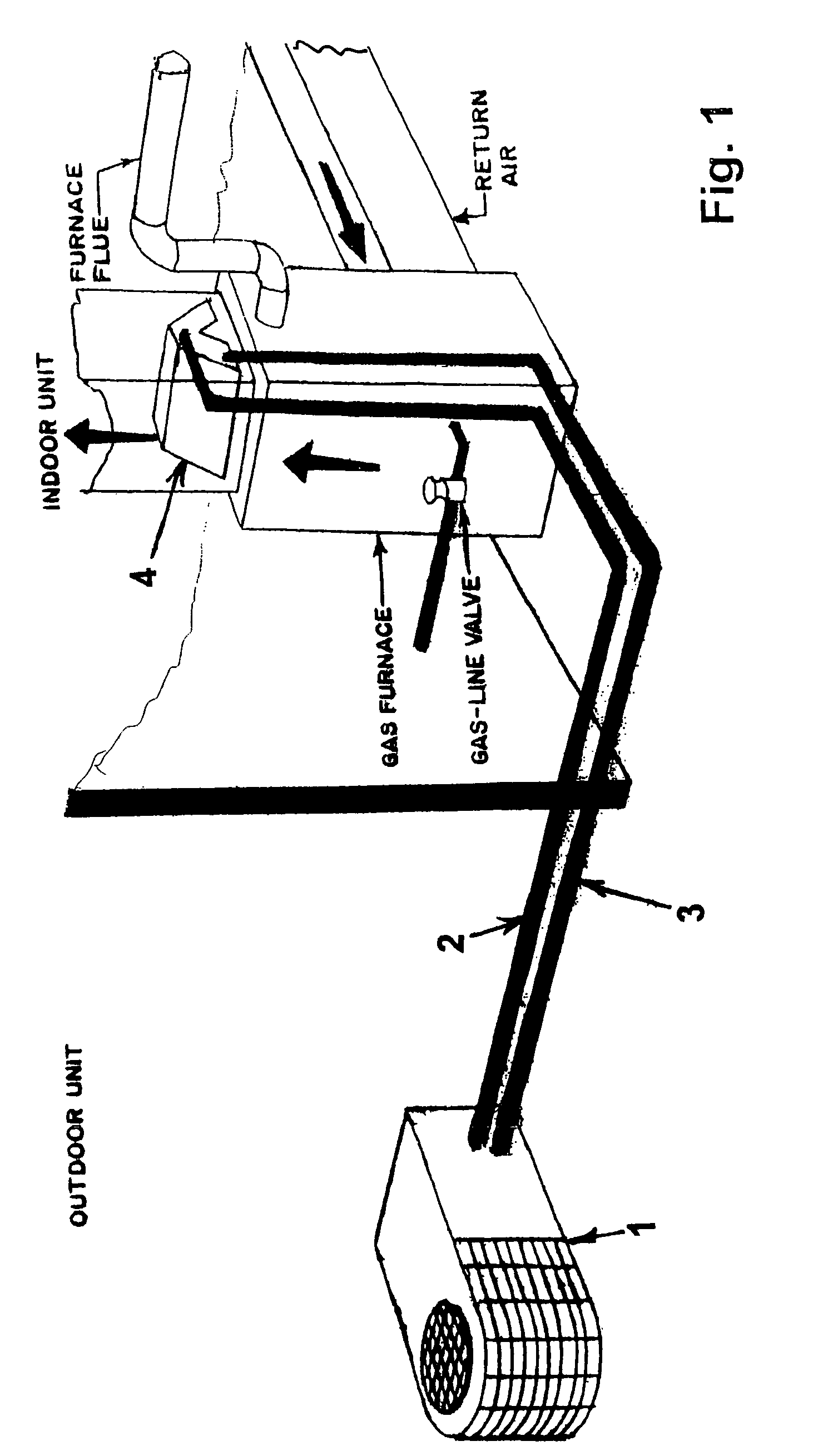
[0015]FIG. 1. In the conventional air conditioning system, the outdoor condensing unit 1 consisting of a compressor, an aluminum finned copper tube condenser coil, a condenser fan to force air across the condenser, and the electrical components such as relays and capacitors needed to operate the system are placed outside the structure to be air conditioned. Copper refrigeration tubing, a liquid line 2 for transferring the condensed refrigerant to the inside evaporator or cooling coil 4 and a suction line 3 to return the evaporated refrigerant gas back to the compressor in the condensing unit. The evaporator 4 is mounted in the supply air or discharge air of the furnace. The furnace is normally natural or propane gas fuel oil or electric. It is not advisable to operate the air conditioning during the heating cycle as this may overheat the refrigerant in the evaporator and ultimately damage the compressor.

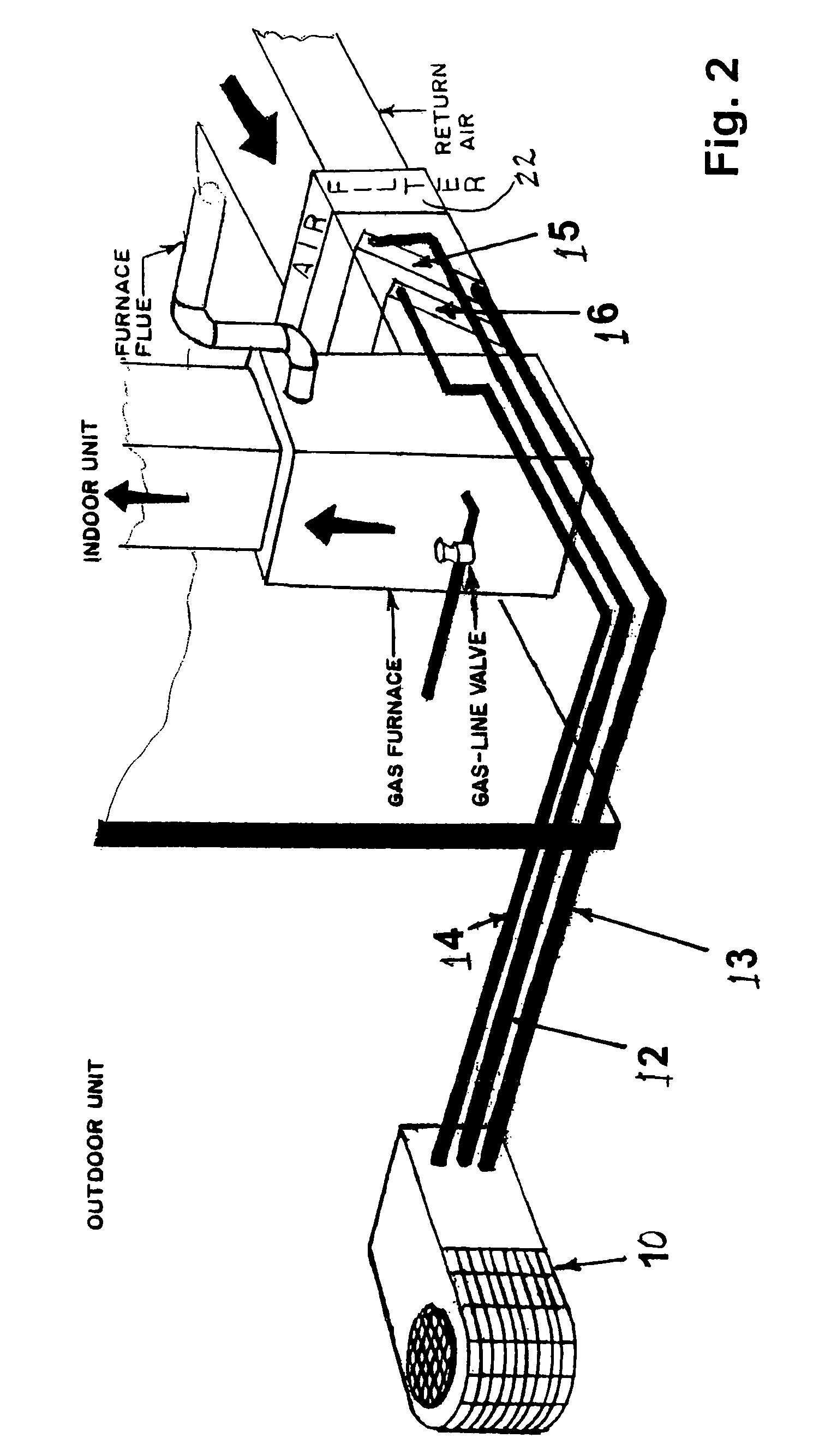
[0016]The conventional heat pump system is approximately the same the addition o...


PUM


Abstract

An air control apparatus having a refrigerant compressor, a condenser, an evaporator coil, and a reheat coil associated with a four way valve to selectively regulate flow of refrigerant to and from the condenser, evaporator coil and reheat coil to control the temperature and humidity of an enclosed environment.

Description

CROSS REFERENCE TO RELATED APPLICATION[0001]This application claims the priority benefit of U.S. Application Ser. No. 60 / 643,048 filed Jan. 11, 2005.FIELD OF THE INVENTION[0002]The invention relates to heating, air conditioning and dehumidification of air supplied to an interior enclosure. Air conditioning and heat pump equipment is used with reheat coils and refrigerant control valves to dehumidify air.BACKGROUND OF THE INVENTION[0003]Comfort is a relative term that is different for virtually every individual because of sex, age, ethnicity, and activity level. Comfort is tied not only to the temperature but also to the relative humidity of an environment. Scientists have also found that a humidity level between 30 and 50 percent discourages many types of mold, dust mites, allergens, and certain bacteria.[0004]There have been air conditioning and heating systems designed to remove humidity from the air. Many of these depended on reheating the cooled air either by use of additional h...

Claims


Application Information

Patent Timeline
IPC IPC(8): F25B49/00F25D17/04G05D22/02F25D17/06
CPCF24F3/153F25B13/00F25B2313/02741F25B2313/02742F25B2313/0292F25B2600/11F25B2700/02
Inventor DILLON, ROBERT J.
Owner DC & BV FRANCE HLDG
Features
  • Generate Ideas
  • Intellectual Property
  • Life Sciences
  • Materials
  • Tech Scout
  • Unparalleled Data Quality
  • Higher Quality Content
  • 60% Fewer Hallucinations
Learn More