Ceramic shroud assembly

a shroud and ceramic technology, applied in the direction of forging/pressing/hammering apparatus, liquid fuel engines, lighting and heating apparatus, etc., can solve the problem of relative large gap (or clearance) between the blade tips and the shroud ring, affecting engine performance, and consuming a lot of energy

Active Publication Date: 2010-08-10
RTX CORP
View PDF48 Cites 58 Cited by
  • Summary
  • Abstract
  • Description
  • Claims
  • Application Information

AI Technical Summary

Problems solved by technology

As a result, in a gas turbine engine incorporating ceramic rotor blades, there is a relatively large gap (or clearance) between the blade tips and the shroud ring.
The leakage reduces the amount of energy that is transferred from the gas flow to the turbine blades, which penalizes engine performance.
In contrast to many metal shroud rings, it is difficult to attach a ceramic shroud ring to a metal gas turbine engine casing because the ceramic material exhibits a low ductility and a lower CTE than the metal casing.

Method used


Image

  • Ceramic shroud assembly
  • Ceramic shroud assembly
  • Ceramic shroud assembly

Examples


second embodiment

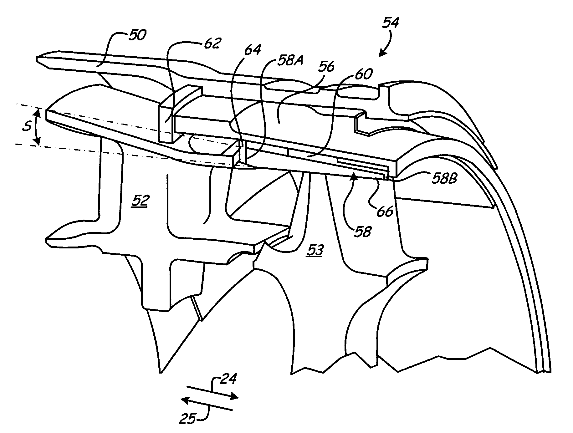
[0045]FIG. 5 is a partial perspective cross-sectional view of turbine engine casing 50, turbine vane 52, turbine rotor 53, and ceramic shroud assembly 54, which is similar to ceramic shroud assembly 20 of FIG. 1, except that shroud 58 is tapered at angle S with respect to line 66, which is parallel to an axial centerline of turbine engine 10, from front face 58A to aft face 58B. In the embodiment illustrated in FIG. 5, angle S is about 10 degrees. Shroud assembly 54 further includes clamp ring 56, which is attached to turbine casing 50, interlayer 60, first axial restraint ring 62, and second axial restraint ring 64. Clamp ring 56 is also tapered to match shroud 58, such that clamp ring 56 and shroud 58 have similar contours. Interlayer 60 is similar to interlayer 30 of FIG. 1. First axial restraint ring 62 helps locate clamp ring 56 such that clamp ring 56 does not move in an upstream direction (indicated by arrow 25).

[0046]Taper angle S of shroud 58 is governed by a frictional coe...

third embodiment

[0047]FIG. 6 is a perspective view of shroud assembly 70 including clamp ring 72 and shroud 74. Shroud assembly 70 also includes an interlayer (not shown) positioned between clamp ring 72 and shroud 74. Shroud assembly 70 is similar to shroud assembly 20 of FIG. 1, except that shroud 74 includes a plurality of anti-rotation tabs 76, which are configured to engage with corresponding openings 78 in clamp ring 72. Anti-rotation tabs 76 circumferentially locate shroud 74 with respect to clamp ring 72, and help limit rotational movement of shroud 74 about center axis 80. In addition, friction between clamp ring 72 and shroud 74 generated by the shrink-fit process helps circumferentially locate shroud 74. In the embodiment shown in FIG. 5, shroud 74 includes three equally spaced anti-rotation tabs 76. However, in alternate embodiments, shroud 74 may include any suitable number of anti-rotation tabs 76, such as two, four, five, etc., as well as any suitable arrangement (e.g., equally or un...


PUM

PropertyMeasurementUnit
thicknessaaaaaaaaaa
thicknessaaaaaaaaaa
angleaaaaaaaaaa

Abstract

A ceramic shroud assembly suitable for use in a gas turbine engine comprises a metal clamp ring shrink fitted around a ceramic shroud ring and an insulating and compliant interlayer. The interlayer is positioned between the metal clamp ring and the ceramic shroud ring.

Description

STATEMENT OF GOVERNMENT INTEREST[0001]This invention was made with Government support under contract number W31P4Q-05-D-R002, awarded by the U.S. Army Aviation and Missile Command Operation and Service Directorate. The U.S. Government has certain rights in this invention.CROSS-REFERENCE TO RELATED APPLICATION(S)[0002]Reference is made to co-pending U.S. patent application Ser. No. 11 / 502,079, entitled TURBINE SHROUD THERMAL DISTORTION CONTROL, filed on the same date as this application.BACKGROUND[0003]The present invention relates to an outer shroud assembly for use in a gas turbine engine. More particularly, the present invention relates to a ceramic shroud assembly including a metal clamp ring shrink fitted around a ceramic shroud ring, where the metal clamp ring is configured to attach to a turbine engine casing.[0004]As gas turbine engine operating temperatures have been elevated in order to increase engine efficiency, many metal alloy (“metal”) gas turbine engine components, su...

Claims


Application Information

Patent Timeline
Patent Type & Authority Patents(United States)
IPC IPC(8): F01D11/18
CPCF01D9/04F01D11/08Y10T29/49323F05D2300/21
Inventor SHI, JUNBUTLER, SHAOLUO L.GREEN, KEVIN E.
Owner RTX CORP
Why Eureka
Try Eureka