Pattern lock system for particle-beam exposure apparatus

a technology of pattern lock and exposure apparatus, which is applied in the field of pattern lock method improvement, can solve the problems of reducing optics and space constraints, and achieve the effect of reducing imaging systems and reducing space restrictions

Active Publication Date: 2010-08-10
IMS NANOFABTION
View PDF15 Cites 28 Cited by
  • Summary
  • Abstract
  • Description
  • Claims
  • Application Information

AI Technical Summary

Benefits of technology

[0014]A first aspect of the invention is applicable in a particle-beam apparatus wherein the imaging of the pattern is done by means of at least two consecutive projector stages of the projecting system, namely, at least one non-final projector stage and one final projector stage, the latter producing the image of the pattern. In contrast to the pattern image, the detection of reference marks images is done at the location of an intermediary image of a non-final projector stage, the registering means being positioned at locations of nominal positions of an intermediary imaging plane. This solution allows to perform the pattern-lock at a place with considerably alleviated space restrictions; moreover, with reducing imaging systems, the intermediate image is at a lower degree of demagnification, so the detection devices can be formed with relieved miniaturiziation.
[0016]Another aspect of the invention uses the exposure pauses between two exposure steps, such as the pausing for movement of the beam to another die field on a wafer. During exposure pauses a lateral movement of the reference mark images is applied by means of the projecting system—in particular, by means of a deflection means such as an electrostatic multipole means—and the resulting varying signals from the image detection are recorded, and based on these signal data a suitable operation point for the position of the reference mark image with regard to the respective registering means is selected. This procedure allows repeated recalibration of the reference system, improving the qualtiy of the pattern-lock control loop.

Problems solved by technology

This layout of the reference device brings about space problems, in particular in reducing optics since the image produced at the target is small and the final optical elements do not allow sufficient room for space-consuming devices such as a scanner block.

Method used


Image

  • Pattern lock system for particle-beam exposure apparatus
  • Pattern lock system for particle-beam exposure apparatus
  • Pattern lock system for particle-beam exposure apparatus

Examples


Embodiment Construction

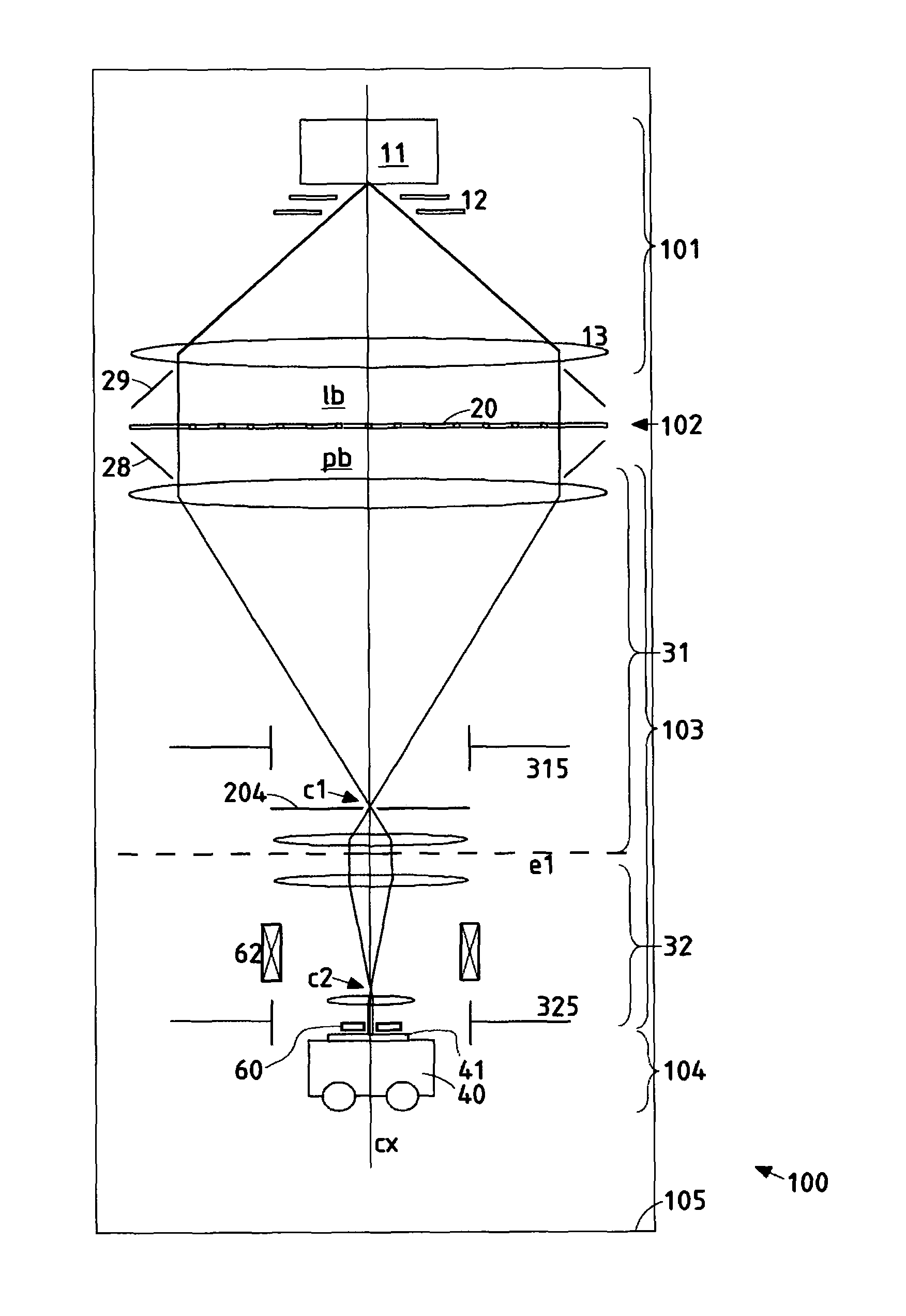
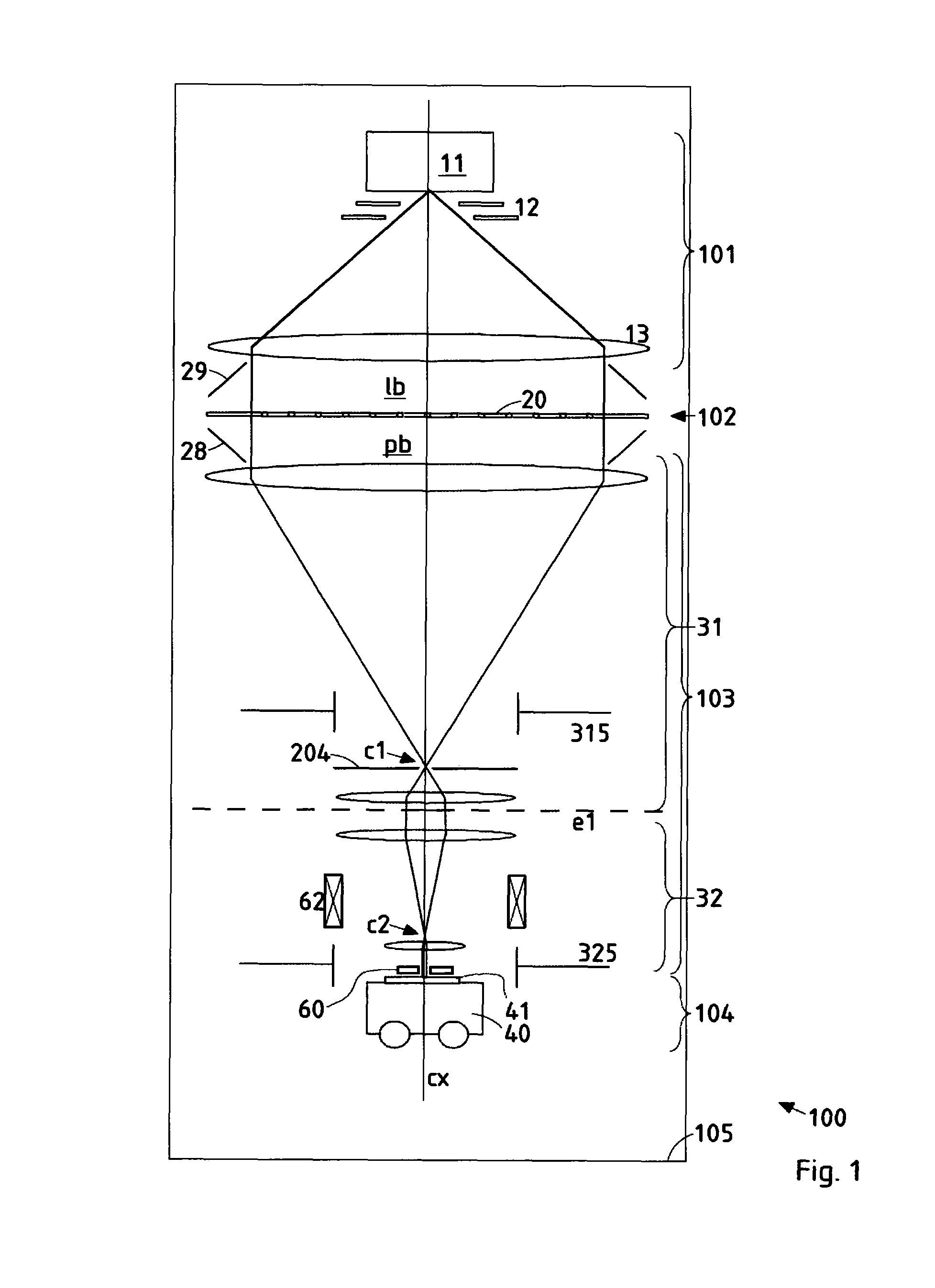
[0038]For the explanations in this disclosure, a Cartesian coordinate system is used with Z denoting the axial coordinate along the optical axis and X, Y denoting the two perpendicular directions.

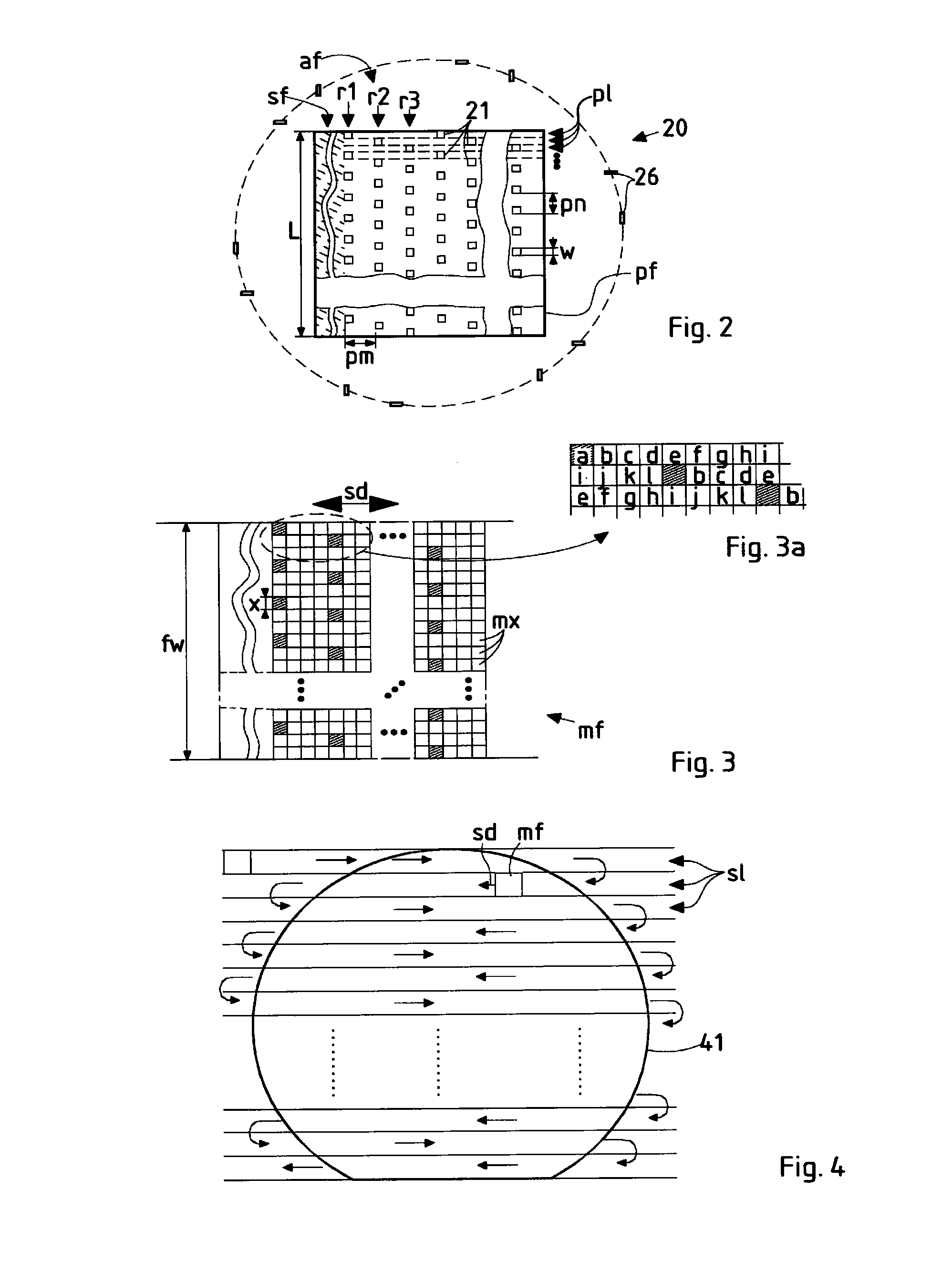
[0039]The preferred embodiment of the invention discussed in the following is based on the pattern definition (PD) system disclosed in the U.S. Pat. No. 6,768,125 (=GB 2 389 454 A) of the applicant (assignee) whose teaching is herewith incorporated into this disclosure. In the following, the technical background of the PD system, as far as relevant to the invention, is first discussed with reference to FIGS. 1 to 4 (which correspond to those of the U.S. Pat. No. 6,768,125), then embodiments of the invention in the PD system are discussed. It should be appreciated that the invention is not restricted to the following embodiments nor the PD system, which merely represent one of the possible implementations of the invention; rather, the invention is suitable for other types of particle-beam ex...


PUM


Abstract

In a pattern-lock system of particle-beam apparatus wherein the imaging of the pattern is done by means of at least two consecutive projector stages of the projecting system, reference marks are imaged upon registering means to determine the position of the particle-beam, at the location of an intermediary image of the reference marks produced by a non-final projector stage, with the registering means being positioned at locations of nominal positions of an intermediary imaging plane. Furthermore, to produce a scanning movement over the registering means the reference beamlets are shifted laterally by means of deflector means provided in the pattern defining means in dependence of a time-dependent electric voltage.

Description

CROSS-REFERENCE TO RELATED APPLICATIONS[0001]This application is a U.S. National Stage Application of PCT Application No. PCT / AT2005 / 000454, filed Nov. 15, 2005, which claims priority from Austrian Patent Application No. A 1927 / 2004, filed on Nov. 17, 2004.FIELD OF THE INVENTION AND DESCRIPTION OF PRIOR ART[0002]The invention relates to improvements of pattern-lock methods for use in a particle-beam processing apparatus. More in detail, the invention relates to a method of controlling the positioning of an image of a pattern in a particle-beam projection processing apparatus during exposure of a target with the image; the pattern is formed in a pattern defining means and is, by means of a beam of electrically charged particles, imaged through a particle-optical projecting system onto the target, in the following conceptual steps:[0003]imaging a number of reference marks provided in the pattern defining means through the same projecting system onto a corresponding number of registeri...

Claims


Application Information

Patent Timeline
Patent Type & Authority Patents(United States)
IPC IPC(8): G21K5/10
CPCB82Y10/00H01J37/3177H01J37/3045B82Y40/00H01J37/3175
Inventor STENGL, GERHARDBUSCHBECK, HERBERTNOWAK, ROBERT
Owner IMS NANOFABTION
Why Eureka
Try Eureka