Electric machine

a technology of electric machines and electric motors, applied in the direction of dynamo-electric machines, electrical equipment, magnetic circuit shapes/forms/construction, etc., can solve the problems of reducing (i) noise, ampere drops, and the impact of performance and cost of electric machines on the overall size and cost of appliances

Active Publication Date: 2010-08-17
NIDEC MOTOR CORP
View PDF45 Cites 20 Cited by
  • Summary
  • Abstract
  • Description
  • Claims
  • Application Information

AI Technical Summary

Problems solved by technology

The size, performance and cost of the electric machine frequently have a significant impact on the overall size and cost of the appliance.
Conventional high-torque, low speed motors with copper windings often have shorter teeth, resulting in reduced (i) noise, (ii) ampere drops in the teeth, and (iii) deleterious flux saturation effects.
Also conventionally, some short teeth were too thin and structurally weak to resist vibration, requiring other mechanical means to strengthen the teeth, such as additional structural members connecting the free ends of adjacent teeth to one another (e.g., wires).
Thus, lower driving currents result in lower wire current (i.e., I2R) losses.
Moreover, excessive saturation can result in non-linear torque per amperage at high torque loads.
Further, in the case of washing machines, motor weight can affect washing machine performance because higher motor weights increase susceptibility of the washing machine to unbalance.
The larger wire gauge allows greater heat transfer, potentially resulting in lower motor operating temperatures.
In addition, prices of conductive materials fluctuate.
At times, some winding materials are more expensive than others.
For example, sometimes copper is very expensive relative to other electrically conductive materials such as aluminum.
However, larger windings raise concerns about machine size and resulting appliance size.
But if the exterior size of the motor is restricted by the application in which the motor is to be used, these increases in length and / or diameter cannot be accomplished and the alternative winding material (e.g., aluminum) cannot be used without sacrificing performance.

Method used


Image

  • Electric machine
  • Electric machine
  • Electric machine

Examples


Embodiment Construction

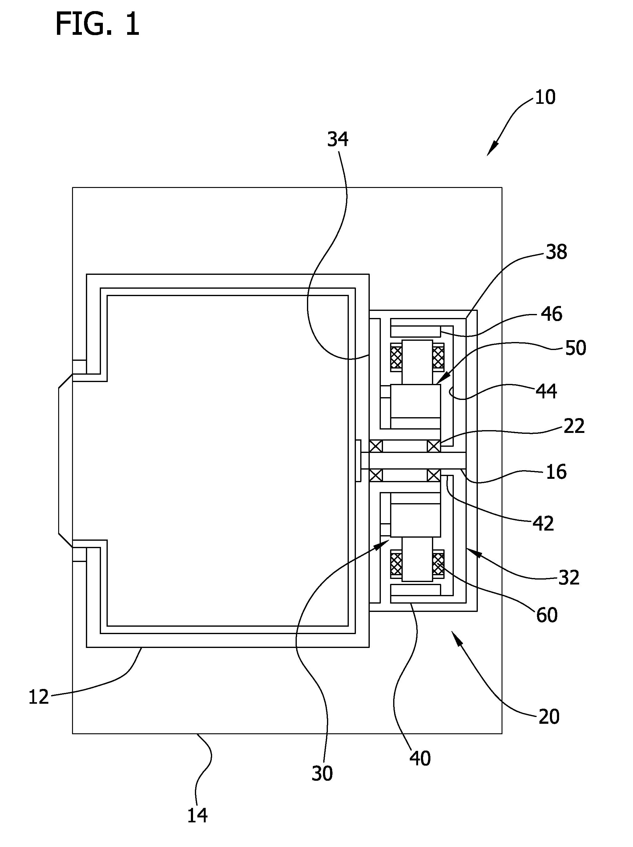
[0019]Referring now to the drawings and in particular FIG. 1, an electric apparatus is designated in its entirety by the reference number 10. In one embodiment, the apparatus 10 consists of a front loading washing machine having a washer drum 12 rotatably supported within a housing 14. A shaft 16 couples the drum 12 to an electric motor, generally designated by 20, positioned behind the drum. Bearings 22 rotatably support the shaft 16.

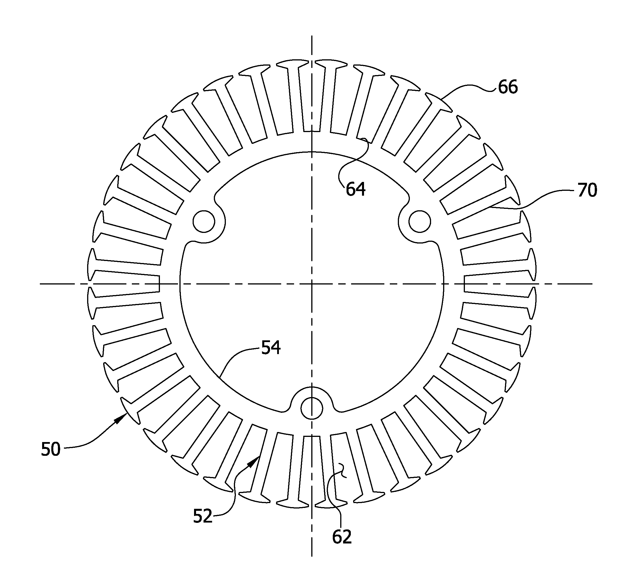
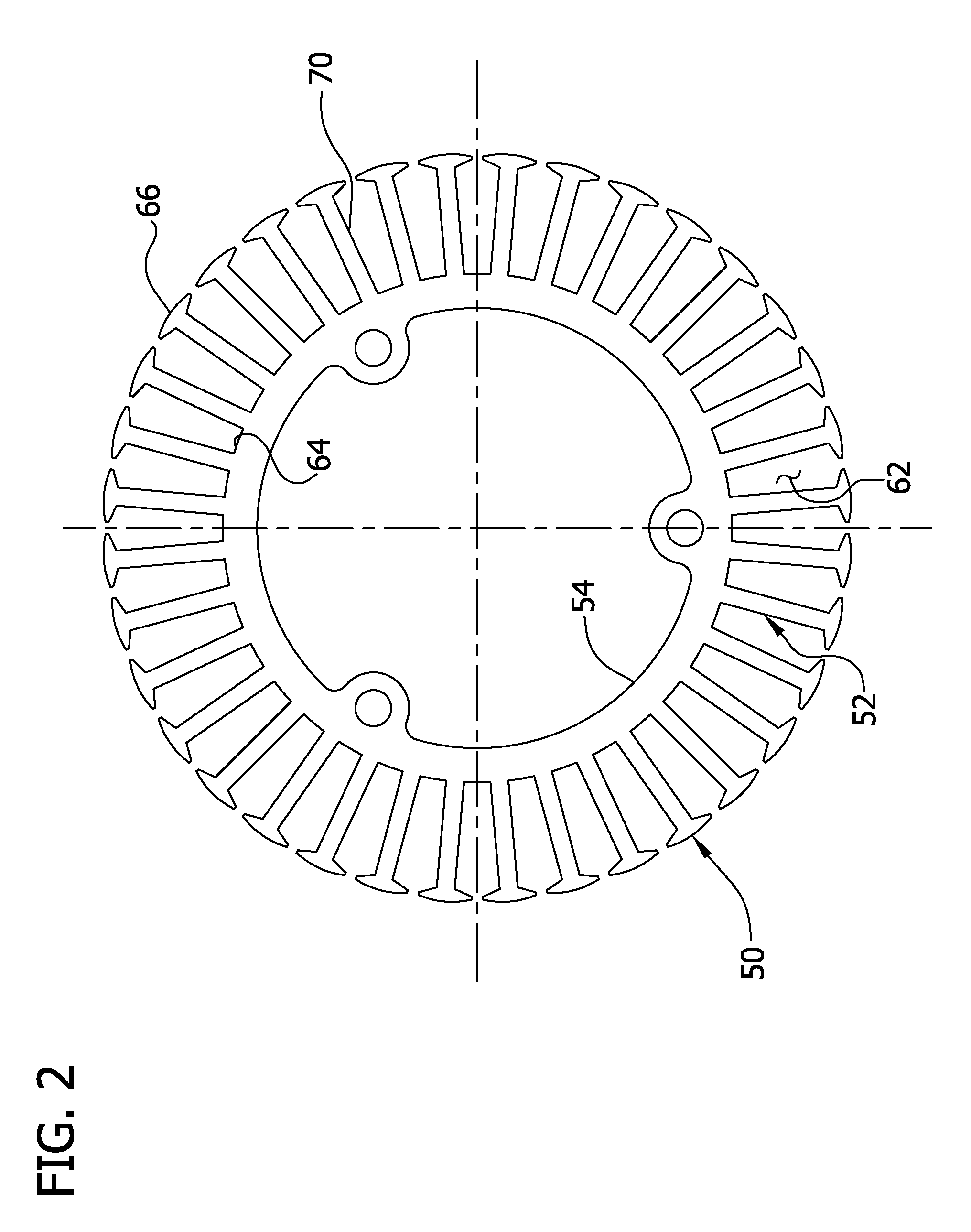
[0020]In one embodiment, the electric motor 20 is an external rotor, brushless permanent magnet (BPM) electric motor mounted in the housing 14 of the washing machine 10. The electric motor 20 includes an internal stator assembly, generally designated by 30, and an external rotor assembly, generally designated by 32. The internal stator assembly 30 is fastened to a mounting bracket 34 positioned in the housing 14 behind the drum 12. The external rotor assembly 32 is coupled to the drum 12 by the shaft 16. The external rotor assembly 32 includes a body 3...


PUM


Abstract

A stator assembly adapted for use in an external rotor electric motor. The assembly includes a stator core having a hub, a plurality of teeth extending radially outward from the hub, a root tooth diameter and an outer diameter. Each tooth has a root, a neck extending from the root and a head opposite the root. The neck has a maximum width. Each adjacent pair of teeth has a pitch measured at the roots of the corresponding teeth. The assembly includes a winding wrapped around each tooth of at least three teeth of the stator core. A ratio of the root tooth diameter of the stator core to the outer diameter of the stator core is less than about 0.75. A ratio of the maximum tooth neck width to the tooth pitch measured at the root of the teeth is greater than about 0.36.

Description

BACKGROUND[0001]The present invention relates to electric machines, such as motors or generators, and more particularly to external rotor, brushless permanent magnet (BPM) electric machines having aluminum windings.[0002]Electric machines, such as motors or generators, typically include a stator mounted inside a housing and a rotor supported in the housing for rotation relative to the stator. The stator and / or the rotor of the machines have windings comprising coils of wire. In motors, electricity is delivered through these coils to generate magnetic fields, causing the rotor to turn. In generators, the electricity is generated in the windings as the rotor turns. Although different electrically conductive materials may be used to make the windings, in the past these windings have frequently been made from copper or copper alloys. Electric machines are often integrated into appliances such as washing machines and apparatus such as stationary bicycles and treadmills. The size, perform...

Claims


Application Information

Patent Timeline
Patent Type & Authority Patents(United States)
IPC IPC(8): H02K1/06
CPCH02K1/146H02K1/16H02K3/02
Inventor HORST, GARY E.
Owner NIDEC MOTOR CORP
Why Eureka
Try Eureka