Method for multiplexed MR tracking

a tracking method and mr technology, applied in the field of nuclear magnetic resonance imaging, can solve the problems of difficult localization, increased cost, and increased cost, and achieve the effect of improving the signal-to-noise ratio (snr)

Inactive Publication Date: 2010-08-17
GENERAL ELECTRIC CO
View PDF45 Cites 21 Cited by
  • Summary
  • Abstract
  • Description
  • Claims
  • Application Information

AI Technical Summary

Problems solved by technology

Because the tracking coils detect signals from their entire surroundings, localization of the MR signal can be difficult when the data pixel size is smaller than that of the coil.
Localization becomes even more difficult when the signal-to-noise ratio (SNR) is relatively low.
Unfortunately, all of these remedies have implications for system cost, resolution (temporal and spatial), and clinical use.

Method used


Image

  • Method for multiplexed MR tracking
  • Method for multiplexed MR tracking
  • Method for multiplexed MR tracking

Examples


Embodiment Construction

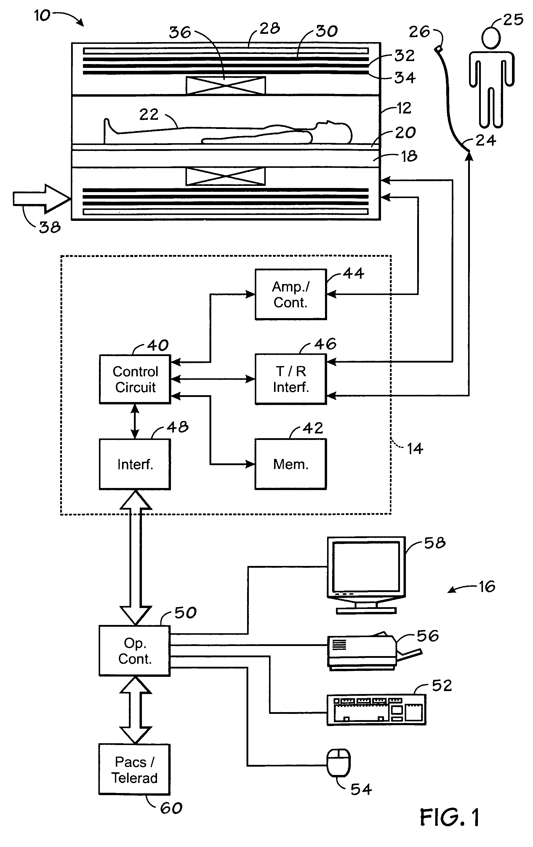
[0021]Turning now to the drawings, and referring first to FIG. 1, an MRI system 10 suitable for MR tracking is illustrated diagrammatically as including a scanner 12, scanner control circuitry 14, and operator interface station 16. While MRI system 10 may include any suitable MRI scanner or detector, in the illustrated embodiment the system includes a full body scanner comprising a patient bore 18 into which a table 20 may be positioned to place a patient 22 in a desired position for scanning. As illustrated in FIG. 1, a device 24 to be tracked may be inserted into patient 22 by an operator 25.

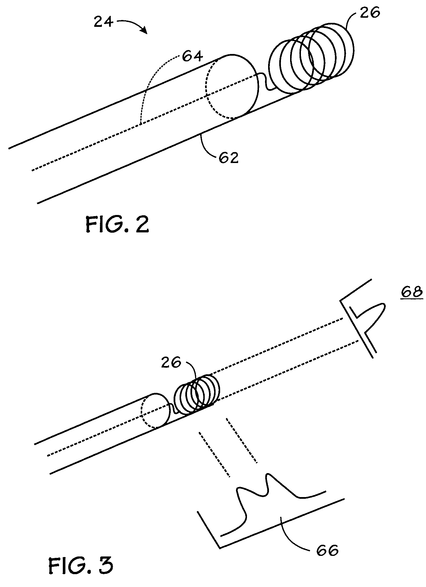
[0022]Device 24 may be may be any suitable device for use in a medical or surgical procedure. For example, device 24 may be a guide wire, a catheter, an endoscope, a laparoscope, a biopsy needle, an ablation device or other similar devices. Non-invasive devices, such as external coils used in tracking, are also within the scope of the present embodiments. As illustrated, device 24 includes an ...


PUM


Abstract

The present technique provides a novel method and apparatus for magnetic resonance device tracking. In one aspect of the present technique, a plurality of magnetic resonance tracking signals are acquired in response to a corresponding plurality of pulse sequences, wherein the plurality of magnetic resonance tracking signals are acquired from a tracking coil mounted in a device. A location value is also determined for each pulse sequence to produce a plurality of location values. Further, a candidate location value of the plurality of location values for replacement, an off-resonance error value for the plurality of magnetic resonance tracking signals, and a replacement location value based on the off-resonance error value are determined. The location of the device is also determined based on the plurality of location values, wherein the candidate location value was replaced in the plurality of location values with the replacement location value.

Description

BACKGROUND[0001]The invention relates generally to nuclear magnetic resonance imaging (“MRI”), and more particularly to a technique for using MRI to determine the location of a device being used in a surgical or medical procedure.[0002]MRI systems have become ubiquitous in the field of medical diagnostics. In general, MRI systems are based on the interactions among a primary magnetic field, a radiofrequency (rf) field and time varying magnetic gradient fields with nuclear spins within the subject of interest. Specific nuclear components, such as hydrogen nuclei in water molecules, have characteristic behaviors in response to external magnetic fields. The precession of spins of such nuclear components can be influenced by manipulation of the fields to obtain rf signals that can be detected, processed, and used to reconstruct a useful image.[0003]The magnetic fields used to produce images in MRI systems include a highly uniform, static magnetic field that is produced by a primary magn...

Claims


Application Information

Patent Timeline
Patent Type & Authority Patents(United States)
IPC IPC(8): G01V3/00A61B5/055
CPCG01R33/287
Inventor DUMOULIN, CHARLESGUHDE, RENEE
Owner GENERAL ELECTRIC CO
Why Eureka
Try Eureka