All optical system and method for providing extended depth of focus of imaging

an optical system and depth of focus technology, applied in the field of imaging techniques, can solve the problems of complicated and expensive fabrication of such lenses, and achieve the effect of simple and high-quality imaging

Inactive Publication Date: 2010-08-17
BRIEN HOLDEN VISION INST (AU)
View PDF8 Cites 22 Cited by
  • Summary
  • Abstract
  • Description
  • Claims
  • Application Information

AI Technical Summary

Benefits of technology

[0006]The present invention solves the above need by providing a novel imaging system allowing obtaining longitudinal super resolved imaging, i.e. extended depth of focus. The invented solution is very simple and involves only the addition of a birefringent element between an imaging lens unit and an imaging detector of a conventional imaging module.
[0007]The birefringent element can be properly designed such that one polarization state from the ordinary and extraordinary ones contains in-focus near field information (positioned at about 20 cm or less from the imaging lens unit) while the other polarization state contains in-focus far field details (positioned from about 50 cm to infinity from the imaging lens unit). Both images are superimposed one on top of the other and thus an all-optical spatially sharp imaging is obtained containing both fields in-focus.
[0016]In some embodiments of the invention, the birefringent element has a curtain surface curvature (rather than being a flat plate), thus providing for improving the depth of focus and for reducing aberrations of focusing.
[0018]In some embodiments of the invention, where a combination of the birefringent element and phase-affecting optical element is used, the birefringent element may be configured for correcting of chromatic aberrations of the imaging lens unit (to provide coinciding focal planes for different wavelengths of input light), while the phase-affecting optical element provides an effect of extended depth of focus.
[0025]According to yet another aspect of the invention, there is provided an imaging method for providing extended depth of focus, the method comprising passing light being focused by an imaging lens and propagating towards an imaging detector (e.g. an individual's retina), through a birefringent element, thereby imaging objects, located at near-field and far-field ranges with respect to the imaging lens, on substantially coinciding imaging planes.

Problems solved by technology

However the fabrication of such a lens is complicated and expensive.

Method used


Image

  • All optical system and method for providing extended depth of focus of imaging
  • All optical system and method for providing extended depth of focus of imaging
  • All optical system and method for providing extended depth of focus of imaging

Examples


Embodiment Construction

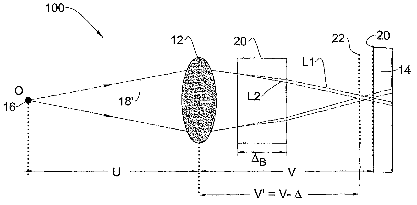
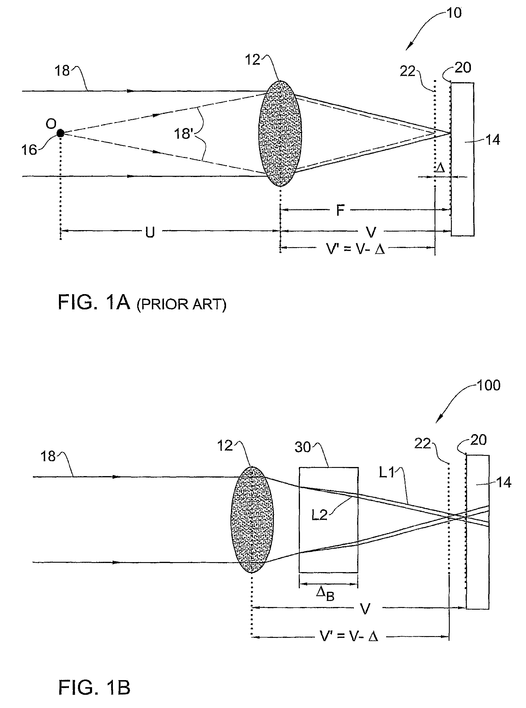
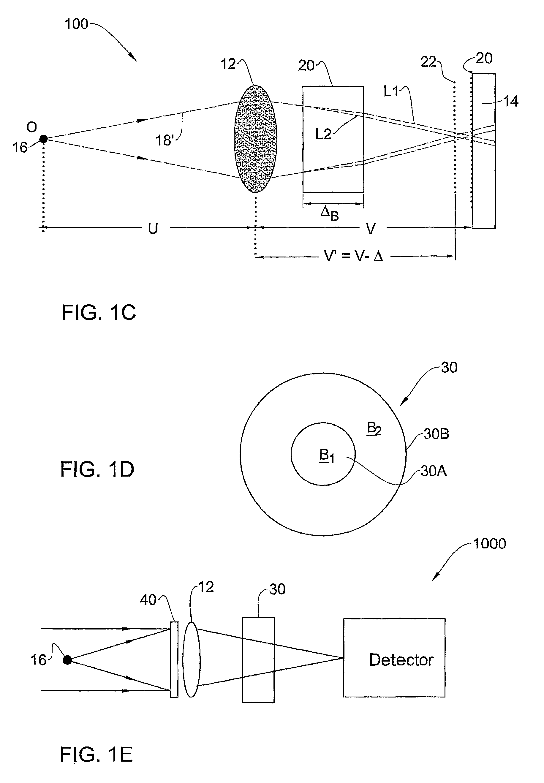
[0040]Reference is made to FIGS. 1A to 1C comparing the configuration and operation of a conventional imaging system (FIG. 1A) and an imaging system of the present invention (FIGS. 1B and 1C). To facilitate understanding, the same reference numbers are for identifying common components in the different imaging systems.

[0041]As shown in FIG. 1A, the conventional imaging system, generally designated 10, includes an imaging (focusing) lens 12 and an imaging detector 14. Here, u (15 cm) is the distance between an object 16 to be imaged and the imaging lens 12, v is the distance between the lens 12 and a sensing surface of the detector 14, and f (5 mm) is the focal length of the lens 12. In such imaging system, typically u>>v≈f. Thus, since the imaging condition is:

[0042]1u+1v=1f(1)

when a large change in u occurs, a very small change in v is required in order to re-focus the image.

[0043]In addition, the conventional imaging system can be adjusted to have good imaging quality, starting fr...


PUM

PropertyMeasurementUnit
thicknessaaaaaaaaaa
thicknessaaaaaaaaaa
focal lengthaaaaaaaaaa

Abstract

An imaging system and method are presented. The system comprises an imaging lens unit, an imaging detector, and a birefringent element located between the imaging lens unit and the imaging detector. The system is thus configure and operable to provide in-focus imaging of objects located at both near-field and far-field ranges. Also provided is an optical device configured to be mounted on an imaging lens, being one of the following: a lens of an individual's glasses, on a contact lens, and an eye internal lens. The optical device is configured to be located between the imaging lens and the retina and comprises a birefringent element, to thereby provide in-focus imaging onto the retina of the objects located at both near-field and far-field ranges therefrom.

Description

RELATED APPLICATIONS[0001]This application is a Continuation of PCT application serial number PCT / IL2007 / 000499, filed on Apr. 22, 2007, which claims the benefit under 35 USC 119(e) of U.S. Provisional Application No. 60 / 793,227, filed on Apr. 20, 2006, both of which are incorporated herein by reference in their entirety.FIELD OF THE INVENTION[0002]This invention is generally in the field of imaging techniques, and relates to an all-optical system and method capable of providing extended depth of focus.BACKGROUND OF THE INVENTION[0003]Extending the depth of focus of imaging systems is a very important technology allowing the system incorporation into various applications, including inter alia medically related applications where elements, such as cameras, are to be inserted into the body in order to observe and detect problematic tissues; as well as ophthalmic industry including glasses for spectacles, contact lenses, intraocular lenses or other lenses inserted surgically into the e...

Claims


Application Information

Patent Timeline
Patent Type & Authority Patents(United States)
IPC IPC(8): G02F1/07
CPCG02B27/0075
Inventor ZALEVSKY, ZEEVBEN-YAISH, SHAI
Owner BRIEN HOLDEN VISION INST (AU)
Why Eureka
Try Eureka