Voltage step-up switching DC-to-DC converter field of the invention

Inactive Publication Date: 2010-08-17
CUK SLOBODAN +1
View PDF5 Cites 37 Cited by
  • Summary
  • Abstract
  • Description
  • Claims
  • Application Information

AI Technical Summary

Benefits of technology

[0078]b) A polarity inverting topology with low and limited voltag

Problems solved by technology

Compared to Mode 2 (FIG. 12b) it introduces higher rms current for the same input-output conversion ratio and

Method used


Image

  • Voltage step-up switching DC-to-DC converter field of the invention
  • Voltage step-up switching DC-to-DC converter field of the invention
  • Voltage step-up switching DC-to-DC converter field of the invention

Examples


Embodiment Construction

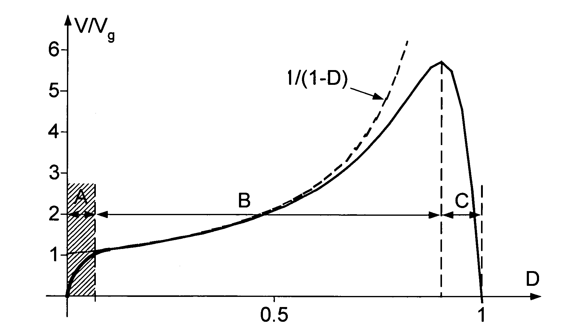
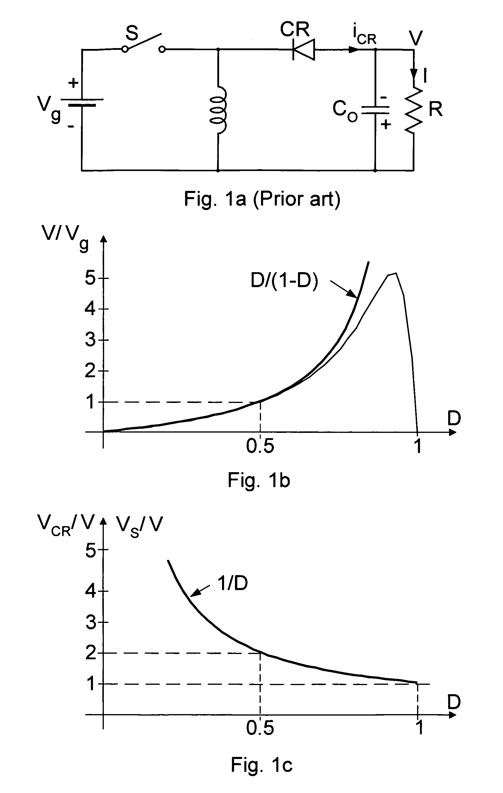
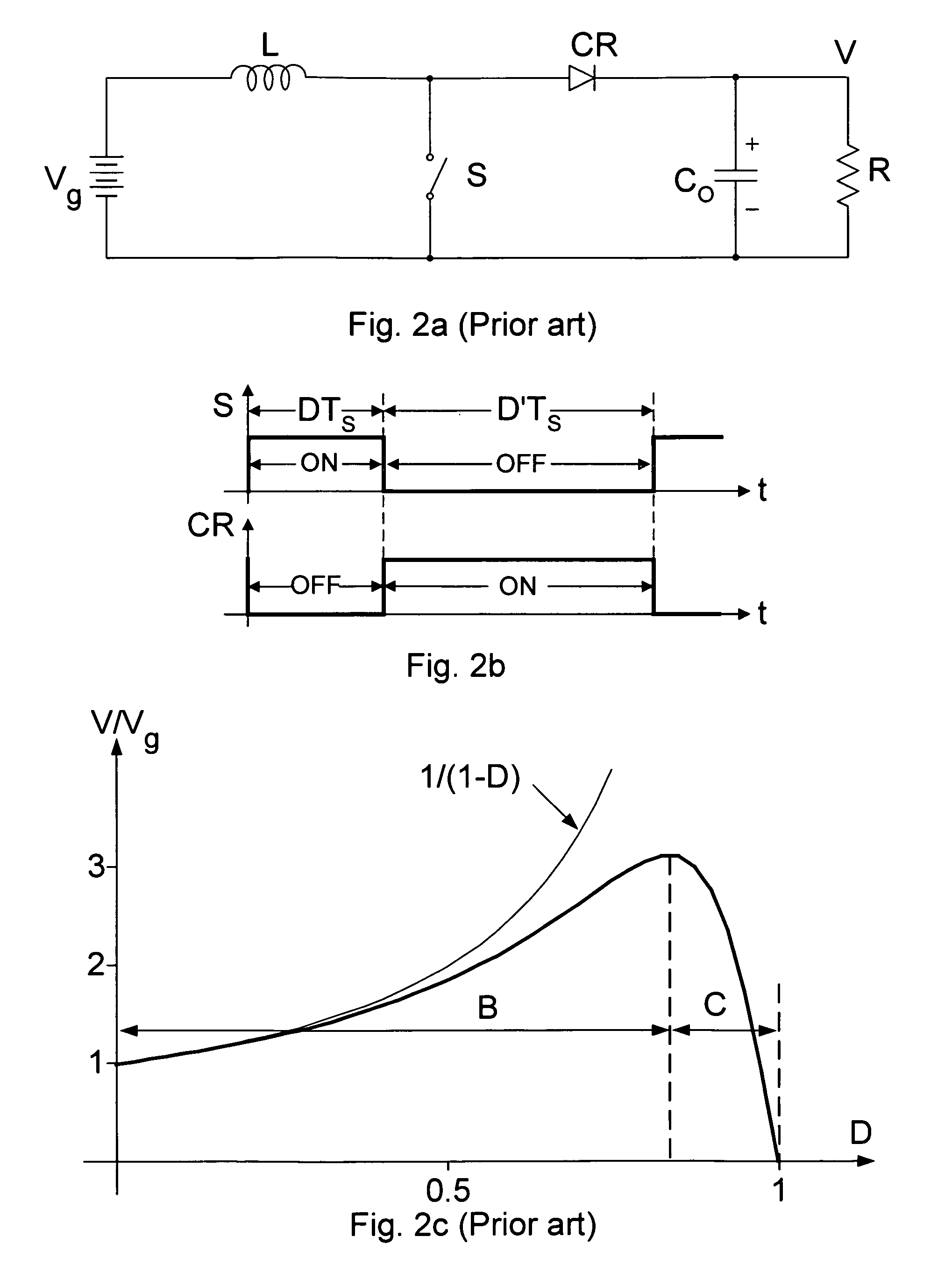
[0146]The best mode of operation is Mode 2 (FIG. 12b) when the resonant discharge interval (half of the resonant period) is equal to the ON-time switching interval. In that case, in addition to lowest conduction losses, the rectifier CR1 turns-OFF under ideal conditions of zero current eliminating undesirable and large turn-OFF losses associated with the reverse recovery current losses which are especially prevalent in high voltage rectification. This in turn also leads to minimum turn-OFF losses of the main active switch S. To regulate the output voltage against input voltage and output current changes, the OFF-time interval must be variable, which effectively results in a variable switching frequency control with constant ON-time interval as discussed next.

Constant ON-Time and Variable OFF-Time Control

[0147]If the ON-time of the main switch S is equal to half of a resonant period, then the resonant discharge current waveform will be exactly half a sine wave. There are several bene...


PUM


Abstract

A non-isolated and isolated both polarity non-inverting and polarity inverting switching DC-to-DC converters with three switches are provided with a basic voltage step-up DC gain characteristics and a very efficient operation without a danger of voltage overstress of any of the three switches over the full operating range from duty ratio of 0 to 1.0, thus resulting in wide input voltage operating range. The isolated extensions feature transformer with no DC-bias for efficient operation and small size. Full-bridge secondary side implementation further reduces the output filtering requirements.

Description

FIELD OF THE INVENTION[0001]The non-isolated switching DC-to-DC converters can be broadly divided into three basic categories based on their input to output DC voltage conversion characteristics: a) step-down only (buck converter), step-up only (boost converter) and step down / step-up (flyback, SEPIC, and Cuk converters). This invention relates to the step-up class of switching DC-to-DC power converters by providing not only polarity non-inverting converter topology (positive input to positive output converter voltage) such as ordinary boost converter but also having a polarity inverting topology capable of generating a negative output voltage from the positive input voltage heretofore not available in present step-up switching converters.[0002]Another classification can be made with respect to the converters ability to have a galvanically isolated version featuring a built-in isolation transformer. Galvanic isolation between the source and load ground is also very often a safety req...

Claims


Application Information

Patent Timeline
IPC IPC(8): H02M3/335
CPCH02M3/157H02M3/33507H02M2003/1557Y02B70/1425Y02B70/1433H02M3/1557Y02B70/10
Inventor CUK, SLOBODANZHANG, ZHE
Owner CUK SLOBODAN
Why Eureka
Try Eureka