

System and method for intracranial access and monitoring
a system and monitoring technology, applied in the field of intracranial access, can solve the problems of catheters not reaching the ventricle, brain trauma, catheters not being able to precisely place the drill stop,
- Summary
- Abstract
- Description
- Claims
- Application Information
AI Technical Summary
Benefits of technology
Problems solved by technology
Method used
Image

Examples
Embodiment Construction
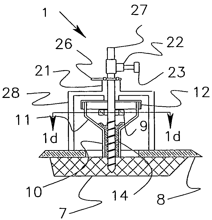
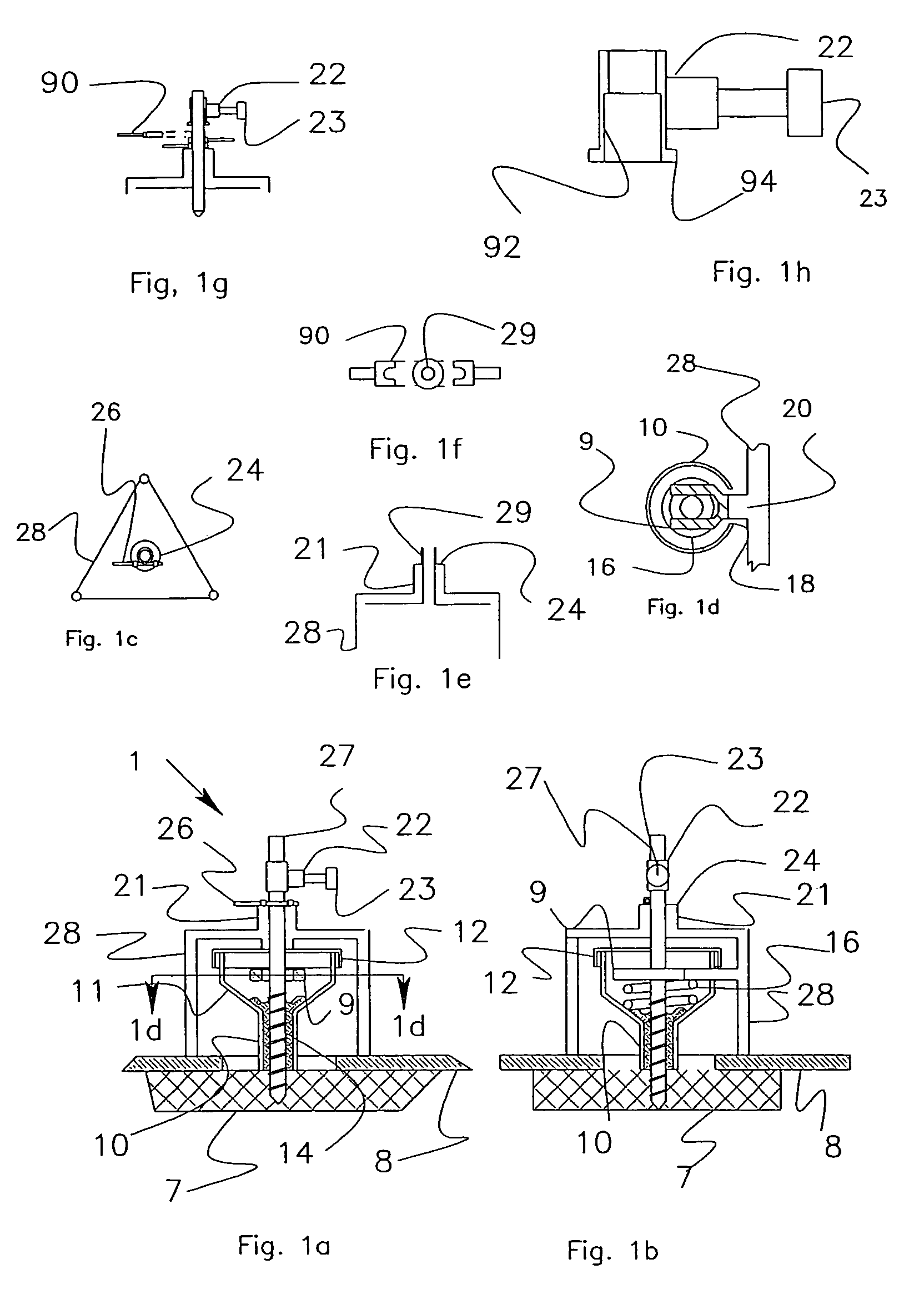
[0044]FIGS. 1a through 1h present a bone collection and drill stop assembly 1. FIG. 1a shows a partial cross section of the assembly. FIG. 1b shows the same assembly rotated 90 degrees. FIG. 1c shows a plan view of a tripod assembly 1. FIG. 1d provides a section 1d-1d that shows a fork element 9 in the tripod that is the upper stop of a spring 16. The spring causes the bone collection device to stay in constant contact with the skull.
[0045]Precision Drill Stop.
[0046]A tripod 28 is placed on a scalp 8 that has been retracted to expose skull bone 7. The tripod has a drill guide 21 through which a drill 27 passes. The tripod drill guide causes the drill guide axis to be aligned perpendicular to an imaginary plane that is tangential to the skull at the drill hole site. The anatomy of the head is such that the axis of the drill guide 21 passes through a ventricle. The forward motion of the drill 27 is constrained by a drill stop 22, which is fixed to the drill bit 27 by a socket screw 23...
PUM
 Abstract
Description
Claims
Application Information