Method for combined bone hardening and scattered radiation correction in X-ray computed tomography

a computed tomography and combined technology, applied in tomography, instruments, applications, etc., can solve the problems of quantitative falsification, errors in excess of 100 hu, and the intensity of the tomography can still be considerable and even exceed the primary intensity

Inactive Publication Date: 2010-08-24
SIEMENS HEALTHCARE GMBH
View PDF8 Cites 4 Cited by
  • Summary
  • Abstract
  • Description
  • Claims
  • Application Information

AI Technical Summary

Benefits of technology

[0008]It is therefore the object of the invention to present a correction method for CT projection data that is improved compared with the prior art and which better compensates the actually occurring scattered radiation and radiation hardening during examination of an object.
[0075]The inventive method and the inventive CT system in particular provide the following advantages:
[0076]The quantitive accuracy of the CT reconstruction, i.e. the accuracy in HU units, may be increased by the iteration cycle, including scattered radiation correction.
[0077]The image artifacts, for example “Hounsfield bars” between bones, caused by radiation hardening and similarly by scattered radiation are significantly reduced.
[0079]The clear mathematical formalization allows a simple generalization to a calculation with a large number of different material components.

Problems solved by technology

Even if anti-scatter grids or special collimators are used to reduce the scattered radiation the intensity thereof can still be considerable and even exceed the primary intensity.
Artifacts consequently result as well as quantitative falsifications following image reconstruction, with errors in excess of 100 HU (=Hounsfield units).
Image errors of up to >100 HU which, for example, occur as bar-like artifacts between prominent bone structures result in this case as well.
In terms of appearance the falsifications generated by hardening or scattered radiation are very similar and it is almost impossible to differentiate them.

Method used


Image

  • Method for combined bone hardening and scattered radiation correction in X-ray computed tomography
  • Method for combined bone hardening and scattered radiation correction in X-ray computed tomography
  • Method for combined bone hardening and scattered radiation correction in X-ray computed tomography

Examples


Embodiment Construction

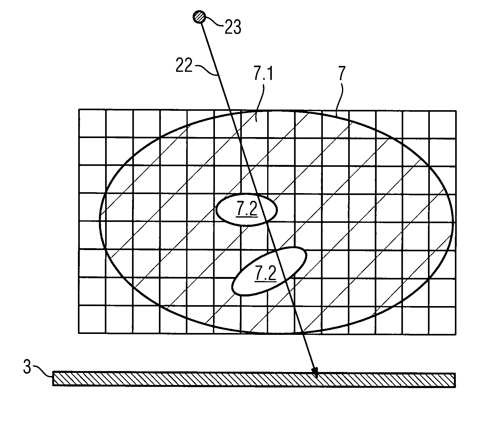
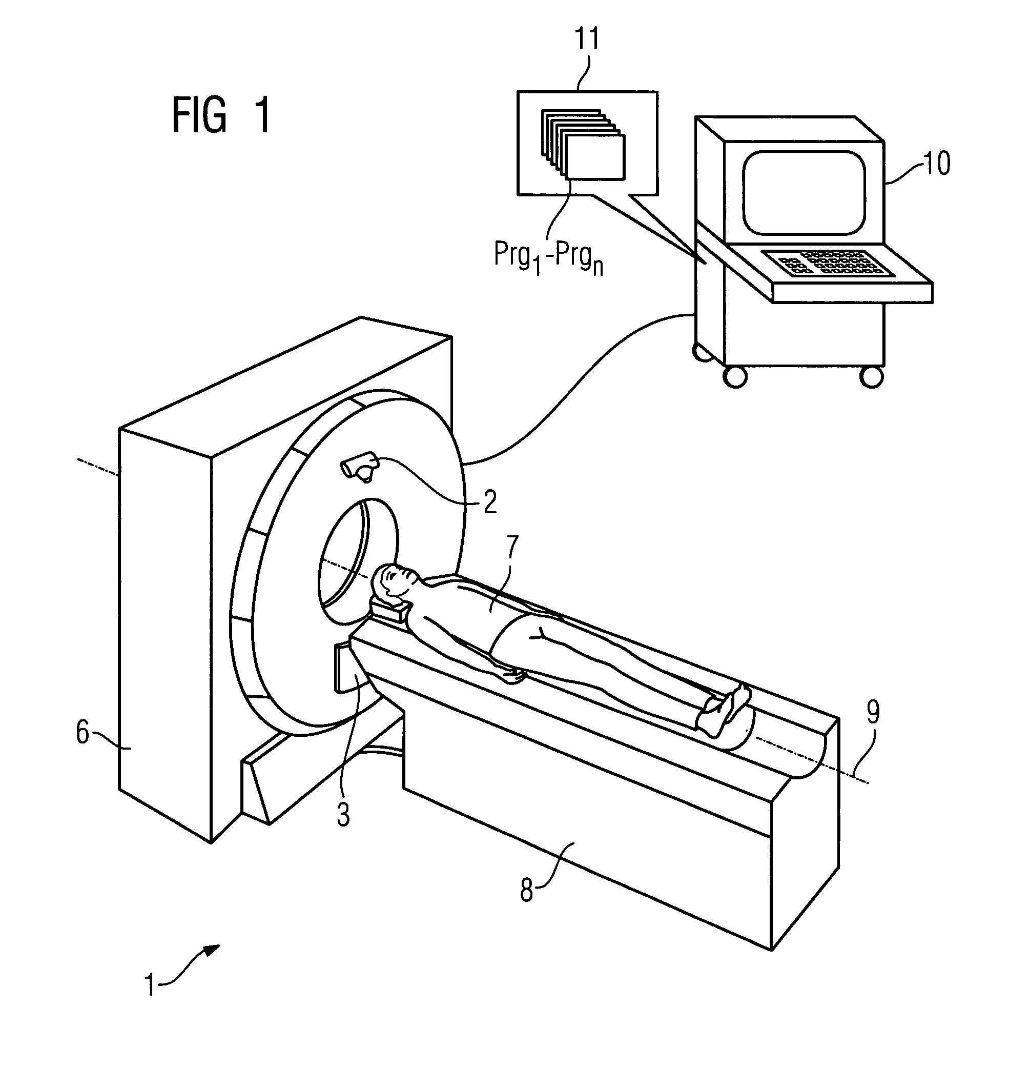
[0088]FIG. 1 shows an inventive CT system 1 with an X-ray tube 2 and an opposing multiline radiation detector 3. The two are mounted on a gantry (not visible here) in a gantry housing 6. For examination the patient 7 is pushed on a movable patient couch 8 along the system axis 9, through the opening between detector 3 and radiation source 2, while the radiation source 2 and detector 3 rotate around the system axis and scan the patient 7. The CT system 1 is controlled by a control and arithmetic-logic unit 10 which has a memory 11 in which computer programs Prg1 to Prgn are stored which during operation assume control of the system and also execute the inventive method with respect to scattered radiation correction and hardening correction.

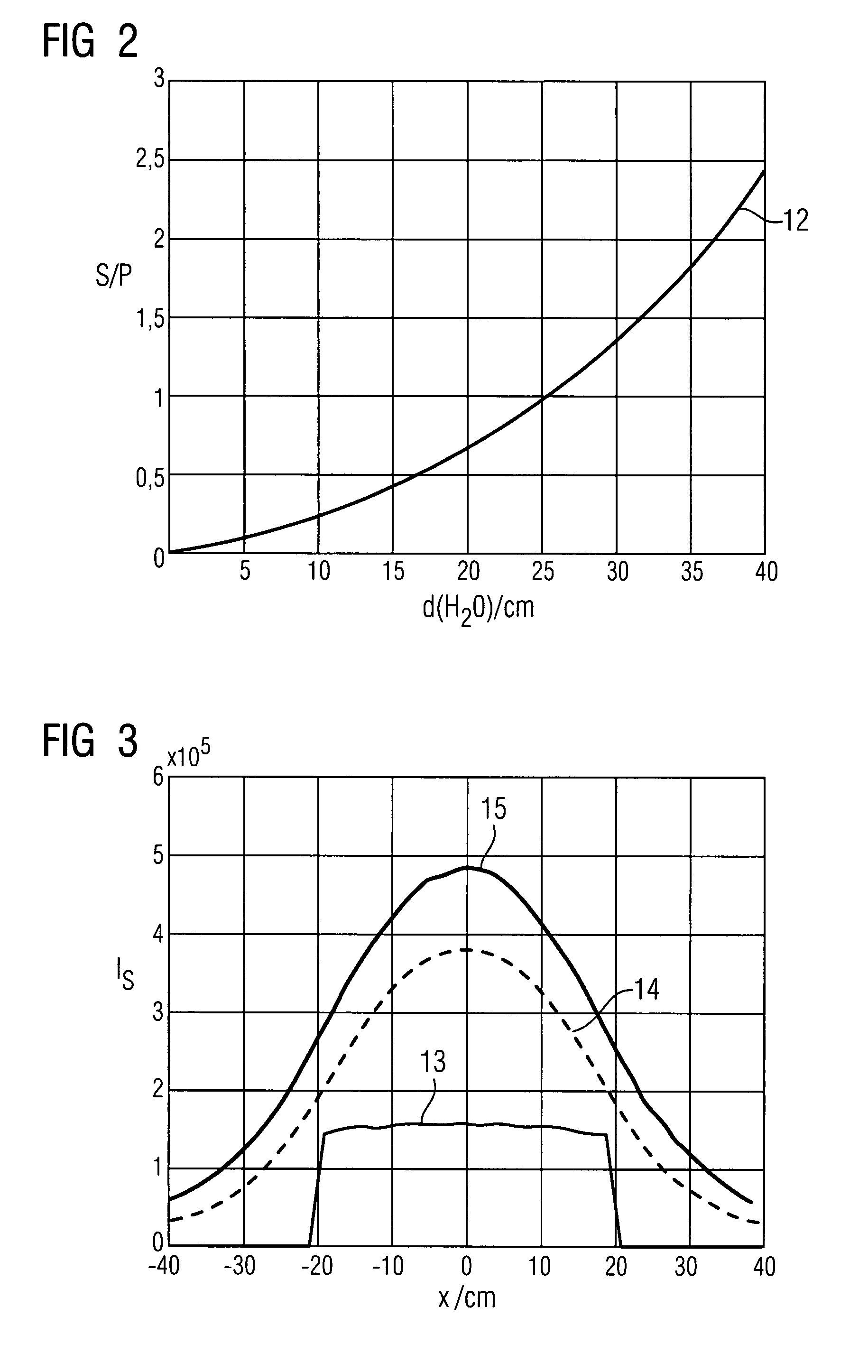
[0089]In FIG. 2 a water layer with a thickness dH2O / cm and that has been penetrated by radiation is plotted on the abscissa and the curve 12 represents the relationship between this water layer thickness with irradiation by X-radiation with a beam ...


PUM


Abstract

The invention relates to a method for combined bone hardening and scattered radiation correction in X-ray computed tomography of a heterogeneous object with a CT system comprising an X-ray source moved around an object, a flat detector with a large number of distributed detector elements which detect measuring beams from a focal point of the X-ray tube, and a control and arithmetic-logic unit—by iterative reconstruction and segmented vectorial reprojection calculation, wherein a scattered radiation correction and a radiation hardening correction are carried out in each iteration cycle for at least two different material components of the object being examined. The invention also relates to an X-ray CT system for carrying out this method.

Description

CROSS REFERENCE TO RELATED APPLICATIONS[0001]This application claims priority of German application No. 10 2006 046 047.2 filed Sep. 28, 2006, which is incorporated by reference herein in its entirety.FIELD OF THE INVENTION[0002]The invention relates to a method for combined bone hardening and scattered radiation correction in X-ray computed tomography (CT) of a heterogeneous object with a CT system, comprising an X-ray source moved around an object, a flat detector with a large number of distributed detector elements which detect measuring beams from a focal point of the X-ray tube, and a control and arithmetic-logic unit. The invention also relates to a CT system which is capable of carrying out such a method.BACKGROUND OF THE INVENTION[0003]Owing to the large solid angle that is captured, scattered radiation plays a significant part in computed tomography with multi-line and flat panel detectors. Even if anti-scatter grids or special collimators are used to reduce the scattered r...

Claims


Application Information

Patent Timeline
Patent Type & Authority Patents(United States)
IPC IPC(8): A61B6/00
CPCA61B6/032A61B6/505A61B6/4291
Inventor RUHRNSCHOPF, ERNST-PETERSCHOLZ, BERNHARD
Owner SIEMENS HEALTHCARE GMBH
Why Eureka
Try Eureka