Implant delivery technologies

a technology of implanted stents and delivery systems, applied in the field of medical devices and methods, can solve the problems of inflexible stent delivery systems, over-the-guidewire and/or sheathed self-expansion stent deployment systems, and inability to accurately deploy them,

Inactive Publication Date: 2010-08-31
BIOSENSORS INT GROUP
View PDF394 Cites 86 Cited by
  • Summary
  • Abstract
  • Description
  • Claims
  • Application Information

AI Technical Summary

Benefits of technology

[0015]In a general aspect, the system is a guidewire-less implant delivery system that includes a noninflatable, elongate delivery guide member having a proximal end and a distal end. The guide member is configured to direct at least one implant having an exterior and interior surface to an anatomical treatment site by manipulation by a user. The at least one implant has a delivery diameter prior to release of the at least one implant and is located proximally of the distal end of the delivery guide member prior to release. The at least one releasable joint is configured to maintain at least a section of the at least one implant at the delivery diameter until release of the at least one releasable joint. The guidewire-less system also has a flexibility and remote directability (e.g. torquability) such that a user may direct the distal end of the guide member into, and introduce, the at least one implant into a coronary artery solely by manipulation of the delivery guide member from its proximal end.

Problems solved by technology

Despite improvements in delivery systems, balloon design, and stent design, these over-the-guidewire and / or sheathed self-expanding stent deployment systems still have their limitations.
For instance, sheathed stents tend to move forward when the sheath is pulled back, deploying them imprecisely.
The sheathed design also requires that the stent delivery system be larger in diameter and less flexible.
Furthermore, for sheathed systems, the interventional procedure may only proceed if the vessel of interest is of sufficiently large diameter to allow sheath placement to avoid significant damage to the luminal surface of the vessel.
Moreover, balloon-expandable stents, by virtue of a large diameter and relative inflexibility, are often unable to reach distal vasculature.
Similarly, occlusive coil placement systems such as systems that deliver detachable platinum coils and GDC® coils also generally do not contain repositionable or step-wise release features.

Method used


Image

  • Implant delivery technologies
  • Implant delivery technologies
  • Implant delivery technologies

Examples


Embodiment Construction

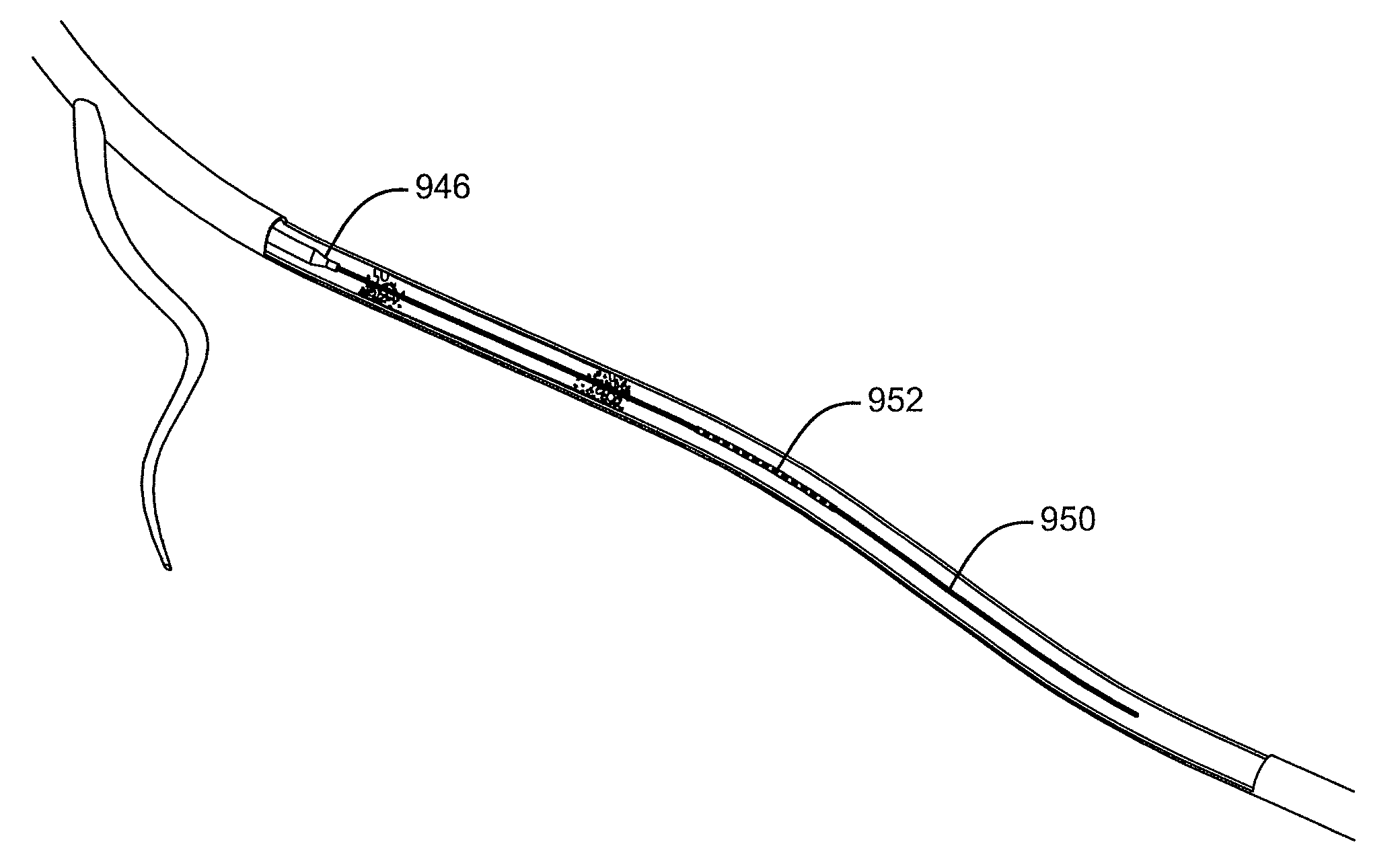
[0042]Described here are devices, systems, and methods for delivering implants into both open and solid regions of the body. The term “region” as used herein refers to luminal structures as well as solid organs and solid tissues of the body, whether in their diseased or nondiseased state. Examples of luminal structures include, but are not limited to, blood vessels, arteriovenous malformations, aneurysms, arteriovenous fistulas, cardiac chambers, ducts such as bile ducts and mammary ducts, fallopian tubes, ureters, large and small airways, and hollow organs, e.g., stomach, intestines, and bladder. Solid organs or tissues include, but are not limited to, skin, muscle, fat, brain, liver, kidneys, spleen, and benign and malignant tumors.

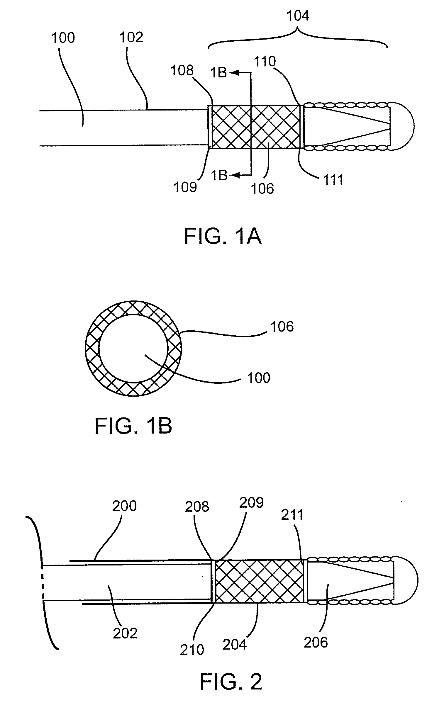
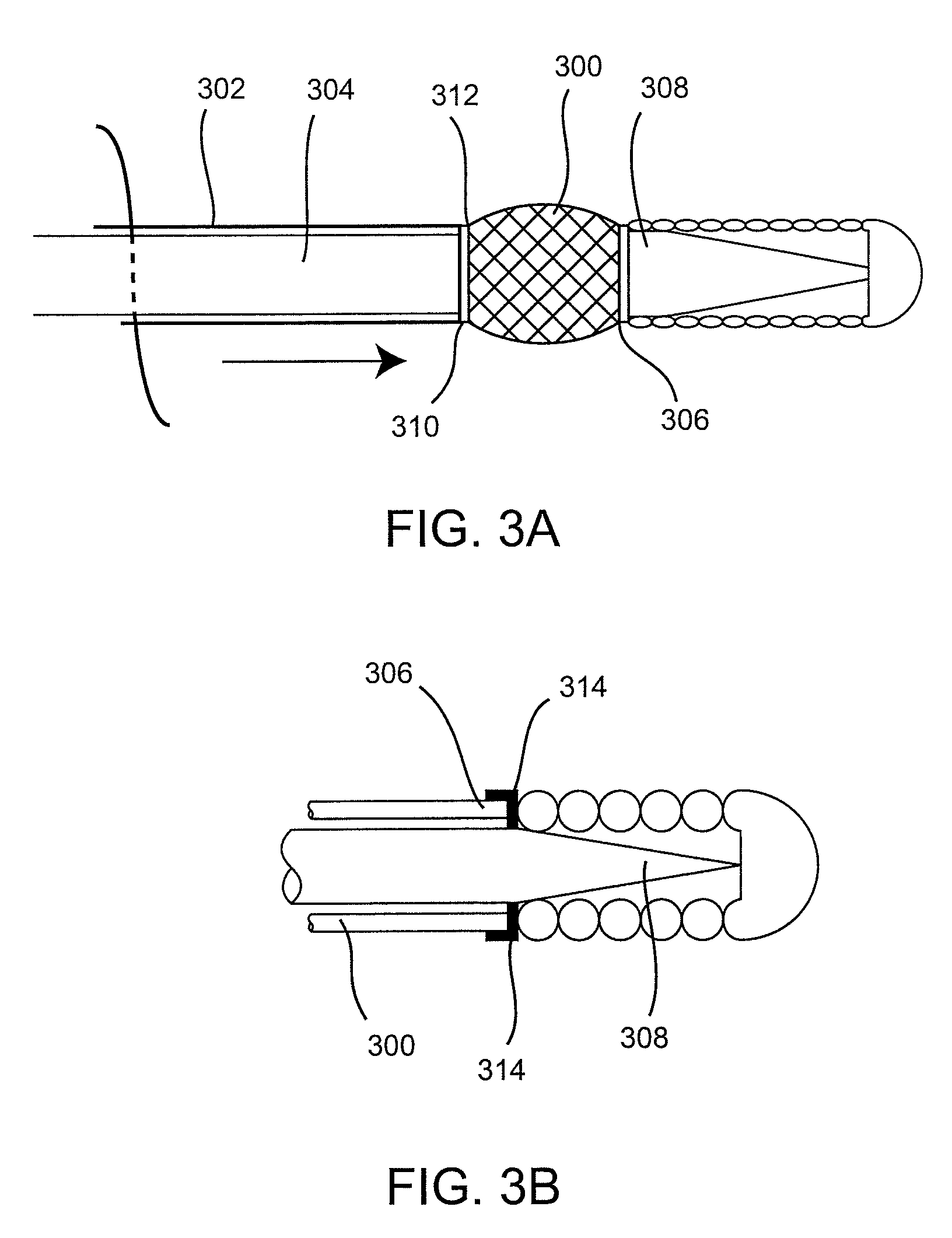
[0043]The device assembly generally includes an elongate, perhaps solid delivery guide, an implant, and one or more implant release mechanisms. Guidewire-less systems are used to deliver the one or more implants. By “guidewire-less” it is meant that the...


PUM


Abstract

Medical devices (100) and methods for delivery or implantation of prostheses (106) within hollow body organs and vessels (600) or other luminal anatomy are disclosed. The subject technologies may be used in the treatment of atherosclerosis in stenting procedures or for other purposes.

Description

CROSS REFERENCE TO RELATED APPLICATIONS[0001]Priority to or the benefit of U.S. Provisional Patent Applications IMPLANT DELIVERY DEVICE (Ser. No. 60 / 458,323), filed Mar. 26, 2003 and IMPLANT DELIVERY DEVICE II (Ser. No. 60 / 462,219), filed Apr. 10, 2003 and U.S. Patent Applications IMPLANT DELIVERY TECHNOLOGIES (Ser. No. 10 / 745,778), MULTIPLE JOINT IMPLANT DELIVERY SYSTEMS FOR SEQUENTIALLY-CONTROLLED IMPLANT DEPLOYMENT (Ser. No. 10 / 746,452), and BALLOON CATHETER LUMEN BASED STENT DELIVERY SYSTEMS (Ser. No. 10 / 746,455), each filed Dec. 24, 2003, and SLIDING RESTRAINT STENT DELIVERY SYSTEMS (Ser. No. 10 / 792,684), now abandoned filed Mar. 2, 2004 is claimed. Furthermore, each of the above-referenced applications is hereby incorporated by reference herein in its entirety.FIELD OF THE INVENTION[0002]The present invention relates generally to medical device and methods. More particularly, it relates to delivery systems for implanting prostheses within hollow body organs and vessels or othe...

Claims


Application Information

Patent Timeline
Patent Type & Authority Patents(United States)
IPC IPC(8): A61F2/06A61FA61F2/01A61F2/88A61F2/90A61F2/91A61F2/95A61F2/958A61F2/966A61F6/00
CPCA61F2/90A61F2/95A61F2/958A61B17/12109A61B17/12022A61B17/1214A61B17/12136A61F2/88A61F2/013A61F2220/0058A61F2/91A61F2002/9505A61F2002/9511A61F2002/9665A61F2250/0071A61B2017/00867A61B19/54A61B2017/1205A61B2017/12063A61F2220/005A61B90/39A61F2/014
Inventor NIKOLCHEV, JULIANTON, DAI T.GEORGE, WILLIAM R.DEBEER, NICHOLAS C.
Owner BIOSENSORS INT GROUP
Why Eureka
Try Eureka