Disk device

a technology of a disk and a head is applied in the field of disk devices, which can solve the problems of data not being read, data not being able to be read, and the accuracy of the following of the magnetic head to the data track is difficult, so as to achieve stable head levitation and head output, the effect of preventing contact between the head and the disk and reducing the thickness

Active Publication Date: 2010-08-31
PHC HLDG CORP
View PDF24 Cites 3 Cited by
  • Summary
  • Abstract
  • Description
  • Claims
  • Application Information

AI Technical Summary

Benefits of technology

[0023]The invention was made in order to solve the problems, and it is an object to provide a disk apparatus having a clamp structure for a disk, whereby the amount and direction of deformation of the disk, which is caused by clamping, are defined, and the head can levitate in a stable manner. Thus, a decrease in head output can be prevented, and the stability and reliability of head output can be improved. Furthermore, the disk apparatus has a fixing structure to the spindle of the disk, which can prevent the occurrence of the distortion of the disk, is stable independently of changes in temperature, and can allow a decrease in thickness and an increase in capacity easily.
[0025]Because of the construction, in the disk apparatus having a head for writing / reading on one side of the disk only, the form of the disk can be a convex form with respect to the side having the head. Thus, stable head levitation can be achieved, and the contact between the head and the disk can be prevented. Furthermore, the flat form of the disk receiving portion has a convex form with respect to the side having the head. Thus, the form of the disk can be convex with respect to the side having the head in the simple construction. Alternatively, in the relationship between distance Rh from the rotational axis center to the contact point or contact plane between the hub and the disk and distance Rs from the rotational axis center to the contact point or contact plane between the disk and the clamp member, which are produced by holding the disk, in the disk apparatus of the invention, the convex form of the disk can be obtained by increasing one on the side having the head with respect to the disk. Thus, stable head levitation can be achieved, and the contact between the head and the disk can be prevented.
[0027]In this construction, the disk is fixed through not only a normally used clamp member but also a spacer ring. Thus, fixing the disk to the hub through the spacer ring, which can provide flatness in a simple form, can reduce the deformation of the disk. Furthermore, the equal or substantially equal linear expansion coefficient or coefficients of the hub and spacer ring does not easily change, independently of a change in ambient temperature, the positional relationship between distance Rh from the rotational axis center of a motor to the contact point or contact plane between the hub and the disk and distance Rs from the rotational axis center of the motor to the contact point or contact plane between the disk and the spacer ring, which are produced by the attachment of a clamp member. As a result, the change in a warp in the direction of the radius of the disk due to a temperature change can be small, and the amount of levitation of the head can be stabilized. The form of the disk can be changed to a convex form with respect to the side having the head independently of the flat form of the disk receiving portion by increasing one having the head with respect to the disk between distance Rh from the rotational axis center to the contact point or contact plane between hub and disk and distance Rs from the rotational axis center to the contact point or contact plane between the disk and the spacer ring, which are produced by holding the disk with the clamp member through the spacer ring. Furthermore, independently of a working temperature atmosphere, the head levitation can be stabilized, and the contact between the head and the disk can be prevented. Still further, the areas where the disk and clamp member are in contact with each other can be small, which can increase the precision of the flatness of the contact planes. In addition, the clamp member is elastically deformed, and the elastic force of which can press the disk against the disk receiving portion of the hub through the spacer ring. Also, a warp of the disk does not cause an unnecessary distortion of the disk.
[0029]This construction allows the distance between the air bearing rails on both ends of the head in the direction of the radius of the disk and the surface of the disk facing thereto to be larger than the distance between the head element substantially in the center part of the head and the surface of the disk facing thereto even when, in the direction of the radius of the disk, the surface of the head facing to the disk is flat or convex toward the disk side. Thus, stable head levitation and head output can be obtained, and the contact between the head and the disk can be prevented. Furthermore, even with a thinner disk, stable head levitation and head output can be obtained. As a result, a decrease in thickness and an increase in capacity are allowed in the disk apparatus.

Problems solved by technology

Upon occurrence of the disk shift, the data track originally coaxial with the rotational center axis is largely decentered, which makes the precise following of a magnetic head (not shown) to the data track difficult.
Furthermore, an increase in costs cannot be avoided even though the surface finish of the clamp area only excluding the data area can be rough technically.
In the conventional disk apparatus as described above, the recent increasing improvement of disk recording density has a problem that data cannot be read because a track shift is caused by displacement of the clamp member due to a change in temperature.
However, the construction of the first example has a problem that the direction and amount of a warp of the disk caused by the clamping of the disk cannot be controlled in a stable manner.
Then, another problem occurs that the amount of levitation of the head is not stable, and, in a worst case, the head touches the disk.
As shown in FIG. 19, another problem occurs that distortions and / or undulations, the number of which is equal to the number of screw threads, occur in the inner part of the disk. FIG. 19 is a diagram showing a deformation of a disk due to the clamping in a conventional disk apparatus.
Furthermore, the amount of warping is increased in the direction of the radius of the disk.
A small modulation deteriorates S / N of a read output signal in accordance with a change in output wave thereof, and an increase in time jitter of data reading pulses reduces the error rate, resulting in inaccurate data writing / reading.
Furthermore, the positioning of head 20 to a target track and / or data writing / reading cannot be performed accurately.
Still further, there is another problem that a decrease in amount of levitation causes a failure such as a contact between disk 1 and the head. FIG. 20 is a head signal output diagram in a conventional disk apparatus.
Therefore, since the direction of the warp of the disk depends on changes in material and temperature, the levitation state of the head changes, resulting in a failure in writing / reading operations of the head disadvantageously.
Furthermore, although the clamp structure in the construction considers to keep the deformation of the disks small or to keep the deformation of the disks caused by a change in environmental temperature small, the complete elimination of the deformation of a disk is significantly difficult with the disk securely maintained flat.
Furthermore, the disks have a small deformation, a sufficient head output cannot be obtained in some direction of the deformation, which is another problem.
Therefore, the recording capacity may not be increased, and the stable levitation of the head cannot be achieved.

Method used


Image

  • Disk device
  • Disk device
  • Disk device

Examples


embodiment 1

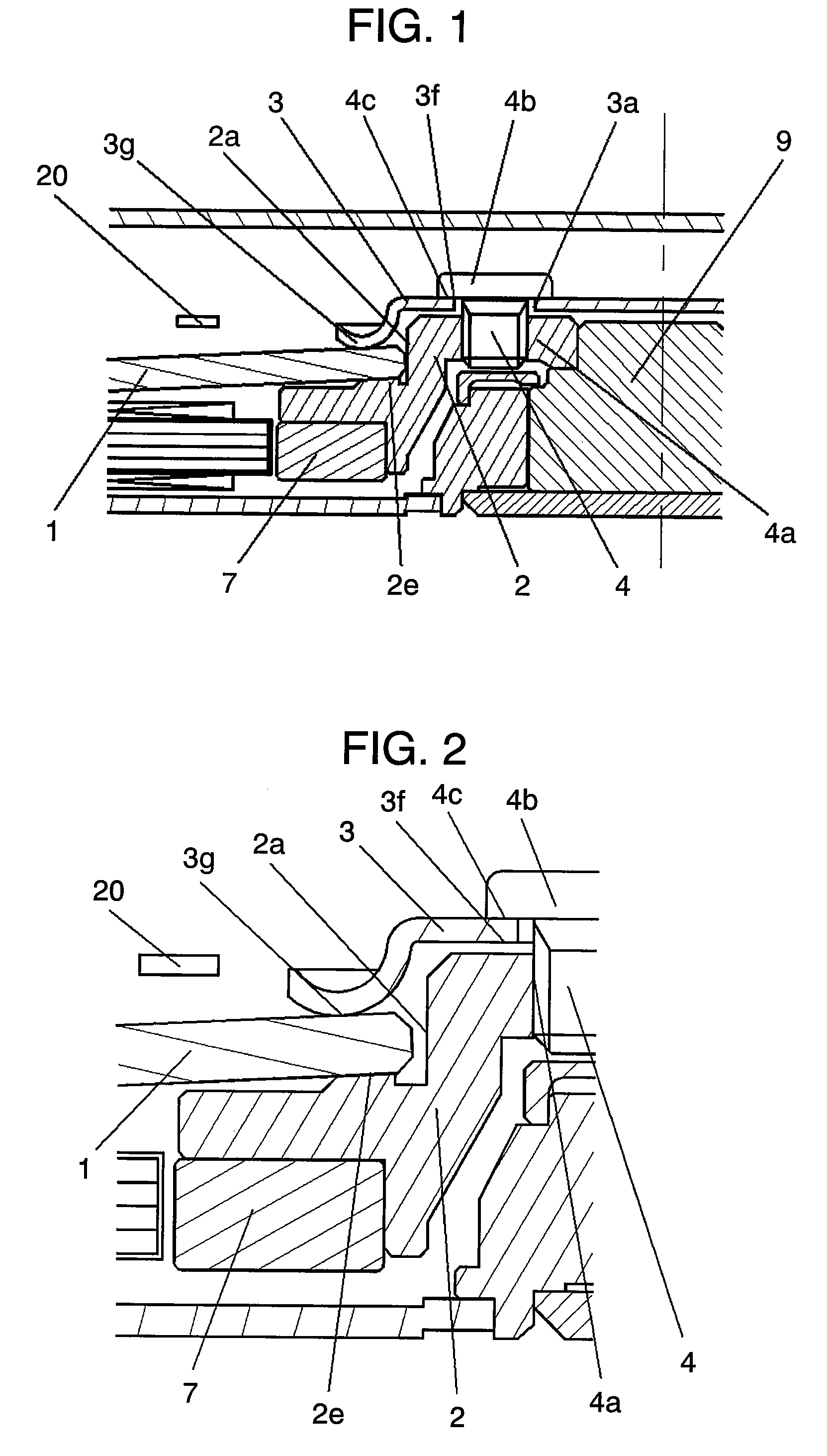
[0092]A disk apparatus according to Embodiment 1 of the invention will be described with reference to FIGS. 1 to 3. FIG. 1 is a partial section view showing a schematic structure of a disk apparatus according to Embodiment 1 of the invention. FIG. 2 is an enlarged section view showing a clamp structure of the disk apparatus according to Embodiment 1 of the invention. FIG. 3 is an enlarged section view showing a clamp structure of another disk apparatus according to Embodiment 1 of the invention. In FIGS. 1 to 3, the same reference numerals are given to the same components as those in FIGS. 16 and 17, which describe the construction of a conventional disk apparatus.

[0093]In FIGS. 1 and 2, disk-shaped recording medium 1 (where a disk-shaped recording medium is abbreviated to disk hereinafter) having a hole in the inner part is inserted to disk inserting portion 2a cylindrically projecting from hub 2. One face of disk 1 is received by the top face of disk receiving portion 2e in the ou...

embodiment 2

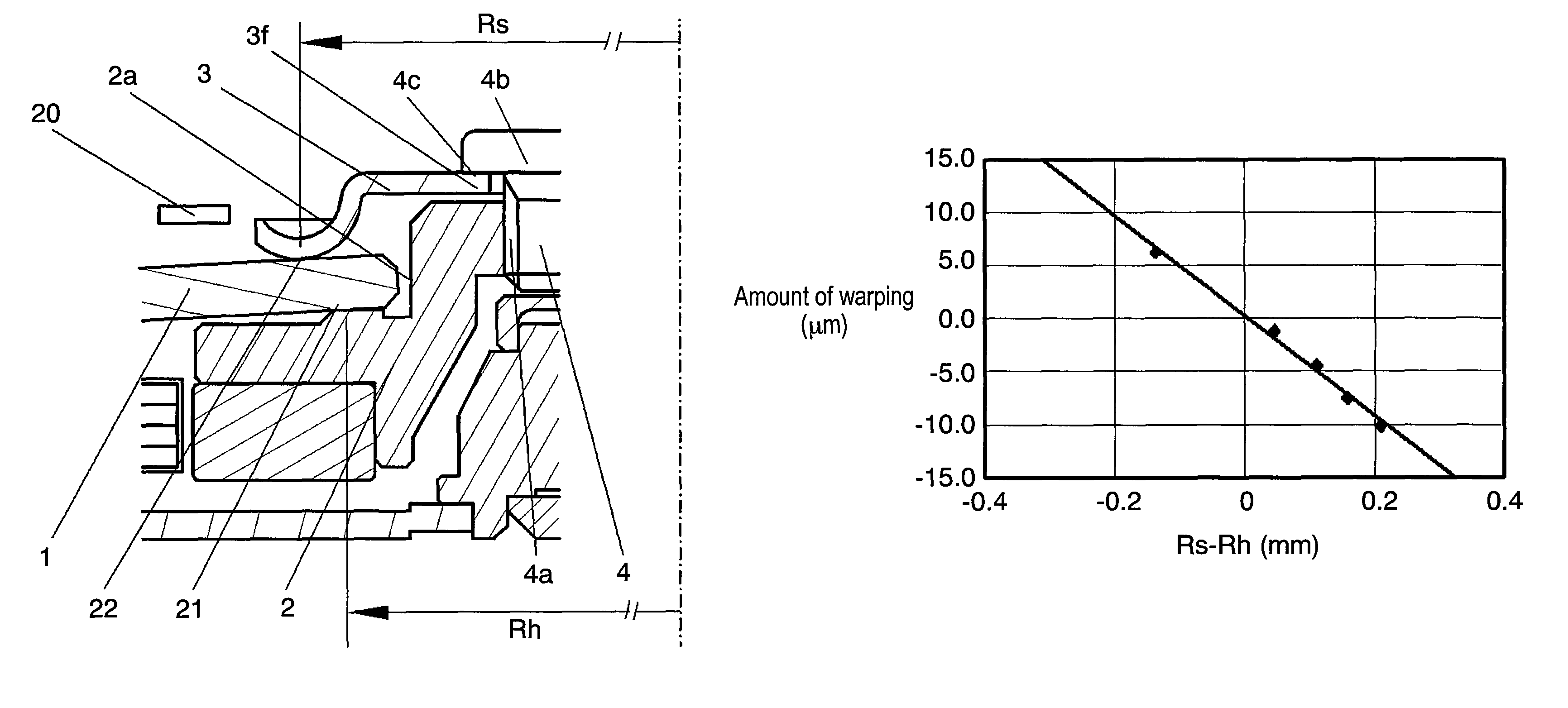
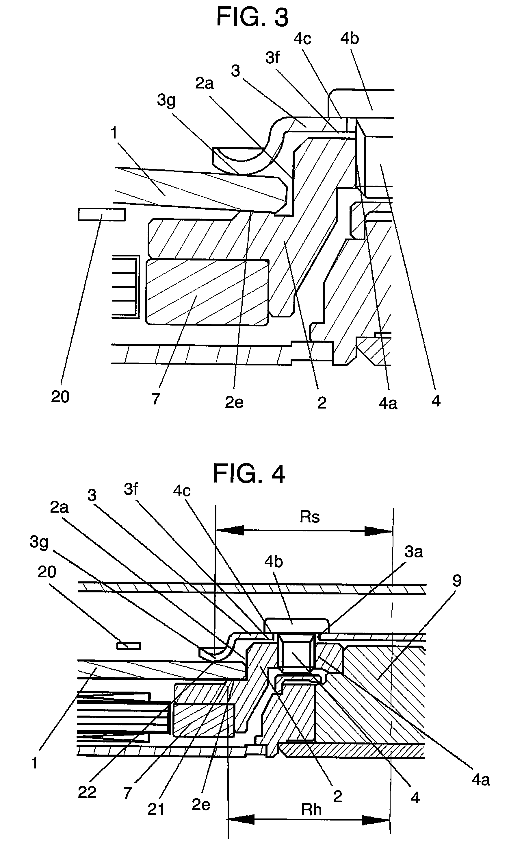
[0097]Next, a disk apparatus according to Embodiment 2 of the invention will be described with reference to FIGS. 4 to 7. FIG. 4 is a partial section view showing a schematic structure of a disk apparatus according to Embodiment 2 of the invention. FIG. 5 is an enlarged section view showing a clamp structure of the disk apparatus according to Embodiment 2 of the invention. FIG. 6 is a correlation diagram showing a relationship between distance Rh and distance Rs and amounts of warps of the disk, which are produced by clamping the disk. FIG. 7 is an enlarged section view showing a clamp structure of another disk apparatus according to Embodiment 2 of the invention. In FIGS. 4, 5 and 7, the same reference numerals are given to the same components as those in FIGS. 1, 2 and 3, which describe the construction of the disk apparatus according to Embodiment 1 of the invention.

[0098]In FIGS. 4 and 5, disk 1 having a hole in the inner part is inserted to disk inserting portion 2a cylindrical...

embodiment 3

[0107]Next, a disk apparatus according to Embodiment 3 of the invention will be described with reference to FIGS. 8 to 15. FIG. 8 is a partial section view showing a schematic structure of a disk apparatus according to Embodiment 3 of the invention. FIG. 9 is an enlarged section view showing a clamp structure of the disk apparatus according to Embodiment 3 of the invention. FIG. 10 is a correlation diagram showing a relationship between contact points Rh between a clamp member and a disk and between the disk and a hub, which are produced by warping of the disk due to clamping and the radius of curvature of the warping of a disk. FIG. 11 includes diagrams describing relationships between the amounts of head levitation and head gaps when the disk warps. FIG. 12 includes diagrams describing relationships between the amounts of head levitation and head gaps due to a warp of a disk when the disk and head have a rate of warping. FIG. 13 is a diagram showing deformation of the disk, which ...


PUM

PropertyMeasurementUnit
Young's modulusaaaaaaaaaa
flatnessaaaaaaaaaa
frictional coefficientaaaaaaaaaa

Abstract

A disk apparatus includes a hub having a disk inserting portion having a cylindrical plane in the outer part of one end and a disk receiving portion having a flat part and being pivotably supported, a head having an inner hole through which the disk inserting portion is fitted, facing toward one face of a disk, levitating and scanning above the disk and reading a signal recorded on the disk or recording a signal on the disk, the disk being held by the disk receiving portion, and a clamp unit holding the disk with the disk receiving portion. In this case, the disk receiving portion has an inclined or declined plane. Thus, the amount and direction of deformation of the disk, which is caused by clamping, are defined, and obtaining a stable amount of head levitation independently of temperature changes can prevent the occurrence of a distortion of the disk.

Description

[0001]This application is a U.S. National Phase application of PCT International Application PCT / JP2006 / 300251.TECHNICAL FIELD[0002]The present invention relates to a disk apparatus to be used for reading / writing information. More specifically, it relates to a thin clamp structure for fixing a disk to a hub in a disk apparatus having a head for writing / reading at least on one side of a disk-shaped recording medium (also simply called disk, hereinafter) that the disk apparatus includes.BACKGROUND ART[0003]In recent years, a large capacity of information can be recorded on a disk having a small recording area with an increase in density of a disk apparatus. Thus, various kinds of technology to be used in a disk apparatus have been developed as recording media for mobile equipment, for example. A recording medium for mobile equipment may be required to be, apparently, small in size and weight, and have low power consumption and shock resistance in consideration of the usages.[0004]FIG....

Claims


Application Information

Patent Timeline
Patent Type & Authority Patents(United States)
IPC IPC(8): G11B17/038
CPCG11B17/0287G11B17/038
Inventor MIYAMORI, KENICHIOBATA, SHIGEONODA, HIROMITSUUENO, YOSHIRO
Owner PHC HLDG CORP
Why Eureka
Try Eureka