
Combined audio coding minimizing perceptual distortion

a combination audio and coding technology, applied in the field of high-quality low-bit rate audio signal coding, can solve the problems of poor performance, poor results in terms of bit rate or quality for certain excerpts of the signal, and no further specification is given to determine the distribution of bit rate between the different encoders, and achieves high efficiency

Inactive Publication Date: 2010-08-31
KONINK PHILIPS ELECTRONICS NV
View PDF15 Cites 8 Cited by
  • Summary
  • Abstract
  • Description
  • Claims
  • Application Information

AI Technical Summary

Benefits of technology

[0008]It is an object of the present invention to provide a flexible audio encoder which is capable of providing high-quality audio encoding with a high efficiency for a large variety of audio signal characteristics and for different target bit rates.
[0017]An audio encoder according to the first aspect is capable of adapting optimal encoding for each excerpt of the audio signal so as to best utilize the two joint encoders to obtain the lowest possible perceptual distortion, i.e. the best perceived quality, given a certain maximum bit rate limit. Especially by choosing the first and second encoders so that they use completely different encoding principles will provide an efficient encoding. For example, for one excerpt with certain signal characteristics, the most efficient encoding may be obtained almost solely with the total bit rate used by the first encoder, while the next excerpt exhibits different characteristics requiring a mix of both encoders for optimal encoding. The encoder according to the first aspect is capable of adapting to different audio signal characteristics and also of providing optimum performance at different maximum bit rate limits. It is known that certain encoders perform best at specific bit rates. This is taken into account due to the optimized mix of the two encoders, thus ensuring that optimum encoding efficiency is obtained for a large range of target bit rates. Encoding parameters of both the first and the second encoder are preferably optimized.
[0018]In principle, an encoder according to the invention allows optimization of the encoding parameters of its separate encoders in accordance with a large variety of criteria. In one embodiment, the optimizing means is adapted to adjust the encoding parameters so as to minimize the distortion measure, i.e. in accordance with this criterion, sound quality is optimized without any consideration of an available bit rate. However, this embodiment may be modified by a constraint of a predetermined maximum total bit rate for the first and second encoders.
[0019]In another embodiment, the optimizing means is adapted to minimize the distortion measure by distributing, within the predetermined maximum total bit rate, first and second bit rates to the first and second encoders, respectively. This audio encoder embodiment seeks to distribute a total bit rate most effectively between the two encoders so as to minimize distortion. In a simple embodiment of two encoders with a limited set of fixed bit rates and a constant sum of bit rates for the two encoders, the optimizing means only needs to adjust the bit rate distribution between the two encoders.
[0020]In other embodiments, the optimizing means is adapted to minimize a total bit rate for the first and second signal parts with a constraint of a predetermined maximum distortion measure. In accordance with this embodiment, the optimizing criterion is to minimize a total bit rate for a fixed measure of distortion.

Problems solved by technology

One encoding method may provide good results for certain types of audio signals, whereas other types of audio signals result in poor performance.
These different characteristics call for different encoding characteristics for optimal encoding, i.e. the use of a single type of encoder may result in quite poor results in terms of bit rate or quality for certain excerpts of the signal.
However, no further specification is given to determine how bit rate is distributed across the different encoders.
No prior-art audio encoder thus addresses the problem of controlling two or more different encoding schemes in response to varying parameters of an audio signal.

Method used


Image

  • Combined audio coding minimizing perceptual distortion
  • Combined audio coding minimizing perceptual distortion
  • Combined audio coding minimizing perceptual distortion

Examples


Embodiment Construction

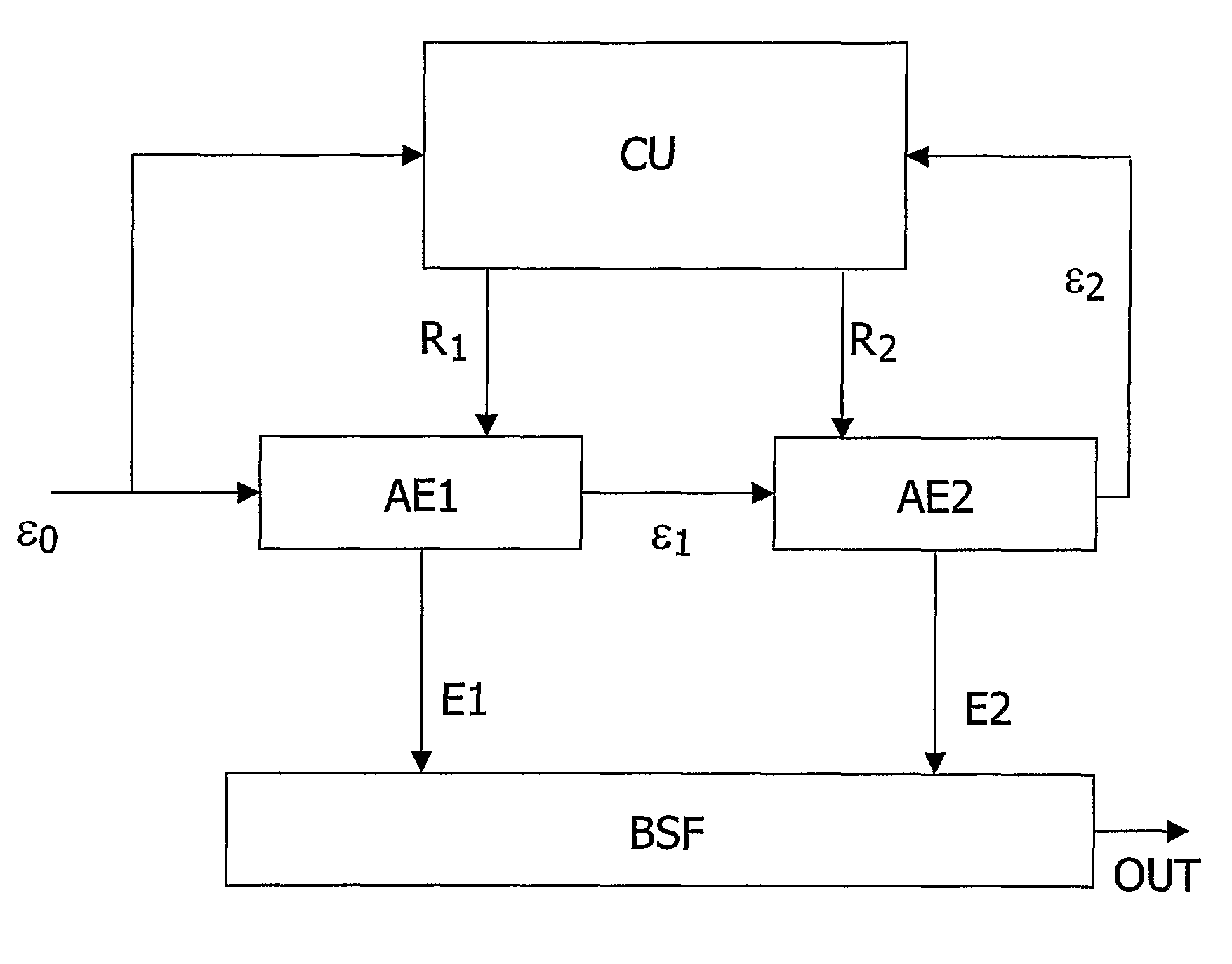
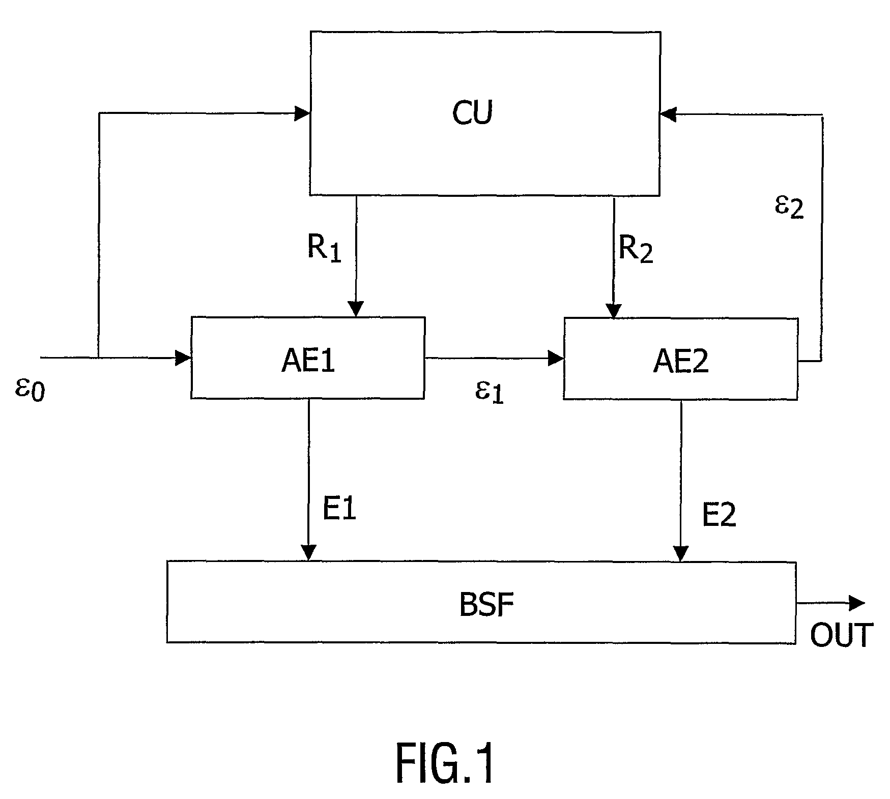
[0062]FIG. 1 is a block diagram illustrating the principles of a first, simple encoder embodiment comprising a cascade of two different encoders AE1, AE2 operating with a fixed total target bit rate per frame. A frame is defined as a time interval which is equal to or larger in duration than a single segment. The first encoder AE1 preferably comprises a sinusoidal encoder, while the second encoder AE2 comprises a transform encoder. The sinusoidal encoding method is efficient at low bit rates and provides a better sound quality compared to waveform encoders at comparably low bit rates. Transform encoders are known to be more bit rate demanding but reach a better sound quality than sinusoidal encoders. Thus, altogether, a combination provides a flexible audio encoder.

[0063]In the encoding scheme shown in FIG. 1, an excerpt of an audio signal ε0 is encoded by the first encoder AE1 using a certain proportion R1 of the target bit rate. The proportion of the bit rate R1 that can be spent ...


PUM


Abstract

An audio encoder in which two or more preferably different encoders cooperate to generate a joint encoded audio signal. Encoding parameters of the two or more encoders are optimized in response to a measure of distortion of the joint encoded audio signal in accordance with a predetermined criterion. The distortion. measure is preferably a perceptual distortion measure. In one encoder embodiment comprising a sinusoidal and a waveform encoder, a constant total bit rate for each audio frame is distributed between the two encoders so as to minimize perceptual distortion for both the first and the second encoder. Other embodiments consider a set of encoding parameters that is larger than only those that minimize the perceptual distortion of the first encoder. In some embodiments, perceptual distortion may be minimized by optimizing encoding via optimizing entire encoding templates, i.e. a complex set of encoding parameters, for the separate encoders. The separate encoders may either be cascaded or operate in parallel, or in a combination of these. Two or more audio segments are preferably taken into account in the optimizing procedure. A corresponding audio decoder comprises separate decoders corresponding to the separate encoders of the audio encoder that encoded the audio signal. Decoded signal parts from these decoders are then added to produce the final audio signal. The presented audio encoding is efficient and provides a high sound quality because the encoding scheme is flexible and adapts to specific demands for each audio excerpt.

Description

FIELD OF THE INVENTION[0001]The invention relates to the field of high-quality low bit rate audio signal coding. The invention particularly relates to effective coding optimized with respect to perceived sound quality, while considering a target bit rate. More specifically, the invention relates to audio signal encoding using a plurality of encoders to produce a joint encoded signal representation. The invention also relates to an encoder, a decoder, encoding and decoding methods, an encoded audio signal, storage and transmission media with data representing such an encoded signal, and audio devices with an encoder and / or decoder.BACKGROUND OF THE INVENTION[0002]In high-quality audio encoding, it is well known that different encoding methods are necessary to provide an optimal result with respect to sound quality versus bit rate for a large variety of audio signals. One encoding method may provide good results for certain types of audio signals, whereas other types of audio signals ...

Claims


Application Information

Patent Timeline
Patent Type & Authority Patents(United States)
IPC IPC(8): G10L19/00G10L19/02G10L19/002G10L19/22
CPCG10L19/22G10L19/002G10L19/18G10L19/04H03M7/30
Inventor VAN DE PAR, STEVEN LEONARDUS JOSEPHUS DIMPHINA ELISABETHVAN SCHIJNDEL, NICOLLE HANNEKEKOT, VALERY STEPHANOVICHHEUSDENS, RICHARD
Owner KONINK PHILIPS ELECTRONICS NV
Learn More