System and method for model based boost control of turbo-charged engines

a turbo-charged engine and model-based technology, applied in the direction of charge feed system, combustion engine, non-fuel substance addition to fuel, etc., can solve the problems of reducing efficiency, conventional control does not adequately address efficiency considerations, and conventional control does not adequately address desire, etc., to achieve accurate boost control, increase engine efficiency, and increase efficiency

Active Publication Date: 2010-09-07
DELPHI TECH IP LTD
View PDF15 Cites 21 Cited by
  • Summary
  • Abstract
  • Description
  • Claims
  • Application Information

AI Technical Summary

Benefits of technology

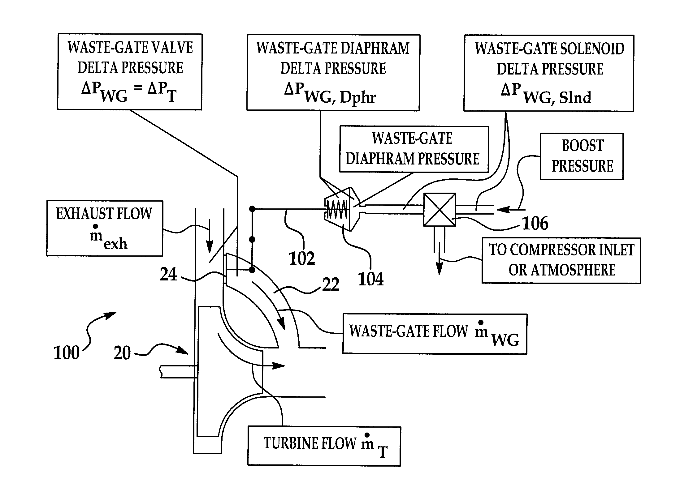
[0006]The present invention provides for increases engine efficiency. The invention enables accurate boost control. This in turn allows setting the desired boost to an optimum, desired boost needed to satisfy requested engine torque without any intake throttling. This results in increased efficiency. Moreover, the invention incorporates the flexibility to work with a variety of waste-gate mechanizations.
[0008]In an alternate embodiment, one use for the method involves determining a desired boost pressure PBoostdes and a desired engine air mass flow rate {dot over (m)}eng,airdes based on a requested engine torque. As above, this allows for increased engine operating efficiency. Of course, the method for controlling boost pressure may be used for many other applications, and is dependent on just a given value for the desired boost pressure PBoostdes as an input.

Problems solved by technology

As to boost control, conventional systems do not adequately address efficiency considerations.
More specifically, conventional controls do not adequately address the desire for producing the optimum amount of boost for a needed amount of engine torque.
As a result, the turbine presents an unnecessarily large restriction to the engine exhaust, which decreases efficiency.
Also, the compressor ends up producing too much boost, which must thereafter be decreased downstream by the intake throttle, also resulting in operating inefficiency.
This unnecessarily decreases fuel economy.
Also, conventional control systems are specific to a particular implementation type, which reduces its applicability to other waste-gate mechanization approaches.

Method used


Image

  • System and method for model based boost control of turbo-charged engines
  • System and method for model based boost control of turbo-charged engines
  • System and method for model based boost control of turbo-charged engines

Examples


Embodiment Construction

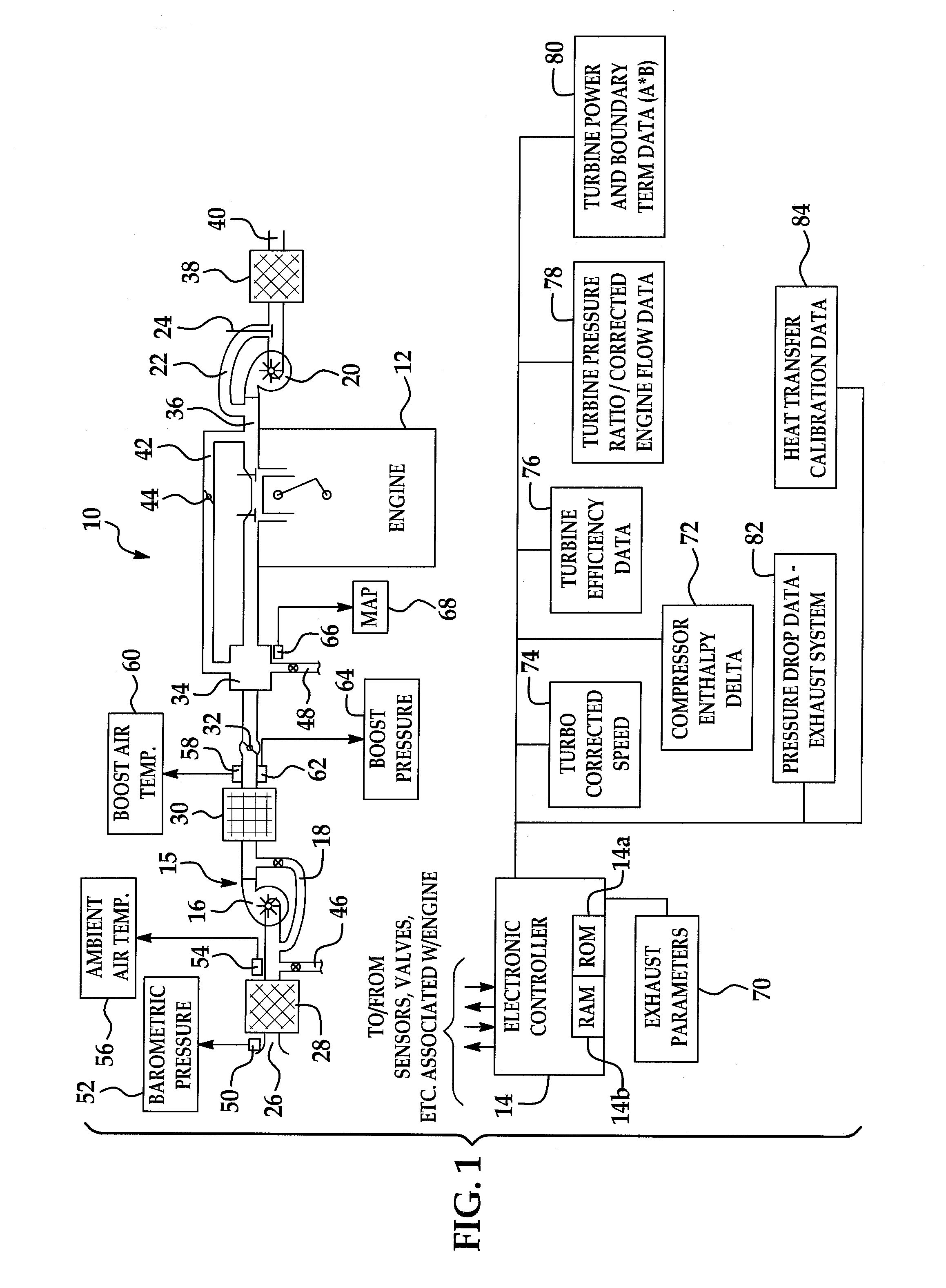
[0019]Referring now to the drawings wherein like reference numerals are used to identify identical components in the various views, FIG. 1 is a diagrammatic view of a turbo-charged internal combustion engine system 10 configured in accordance with the present invention. The system 10 includes an internal combustion engine 12 controlled by an electronic engine controller 14 all in accordance with the present invention.

[0020]Engine 12 may be a spark-ignition engine that includes a number of base engine components, sensing devices, output systems and devices, and a control system. Alternatively, the present invention may be used with compression-ignition engines, such as diesel or the like.

[0021]Generally, electronic controller 14 is configured via suitable programming to contain various software algorithms and calibrations, electrically connected and responsive to a plurality of engine and vehicle sensors, and operably connected to a plurality of output devices. Controller 14 includes...


PUM


Abstract

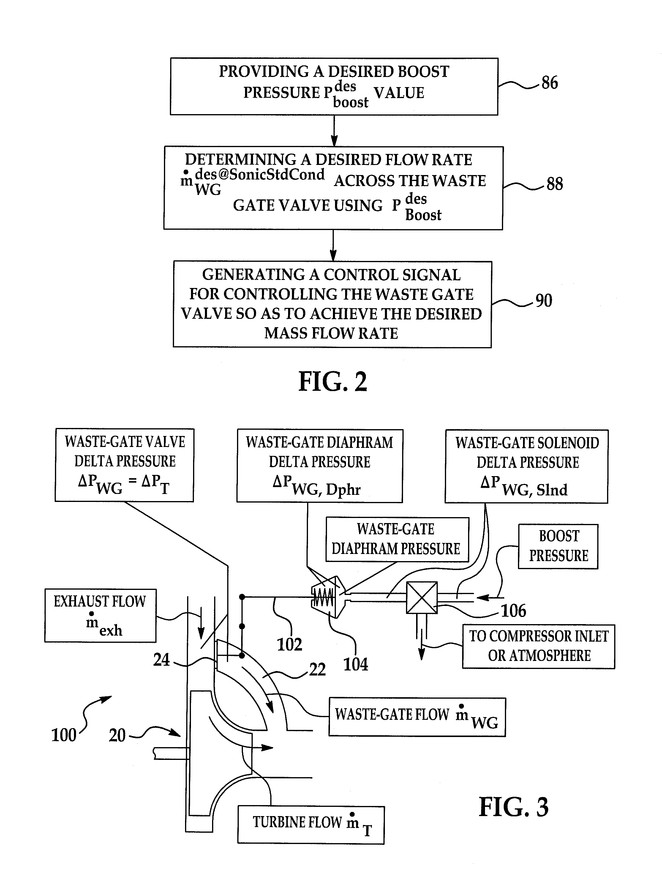
A system and method for controlling boost pressure in various turbo-charged engine configurations as well as variable geometry turbine (VGT) arrangements includes an electronic controller programmed to receive a predetermined desired boost pressure PBoostdes. A desired pressure delta ΔPWGdes across a waste-gate valve is determined using the desired boost pressure PBoostdes. A control signal is generated for controlling the waste-gate valve so as to achieve the desired pressure delta ΔPWGdes. In boost pressure and vacuum pneumatically-actuated waste-gate valve arrangements, the respective solenoid duty cycles are obtained through use of various data structures. Where a waste-gate valve position is controlled by an electrical motor, the valve position is determined using a data structure as a function of desired waste-gate valve flow at sonic standard conditions.

Description

RELATED APPLICATIONS[0001]This application is related to co-pending application entitled “SYSTEM AND METHOD FOR MODELING TURBO-CHARGED ENGINES AND INDIRECT MEASUREMENT OF TURBINE AND WASTE-GATE FLOW AND TURBINE EFFICIENCY,” Ser. No. 11 / 867,422 owned by the common assignee of the present invention and herein incorporated by reference in its entirety.TECHNICAL FIELD[0002]The present invention relates to a system and method for model based boost control of turbo-charged engines.BACKGROUND OF THE INVENTION[0003]A turbo-charged internal combustion engine includes additional components and physical processes in both the intake and exhaust stream. On the intake side of the engine, a centrifugal compressor and intercooler are provided and are located between the air cleaner and a throttle valve. On the exhaust side, a turbine and a waste-gate—which defines a parallel exhaust stream path with the turbine—are both located between the exhaust manifold and the catalyst / muffler. It is known to p...

Claims


Application Information

Patent Timeline
Patent Type & Authority Patents(United States)
IPC IPC(8): F02D23/00
CPCF02B37/12F02B37/18F02B37/24F02M25/0707Y02T10/144F02M26/05Y02T10/12
Inventor MULLER, MARTIN
Owner DELPHI TECH IP LTD
Why Eureka
Try Eureka