Unmanned ocean vehicle

a technology of unmanned ocean vehicles and ocean vehicles, applied in the field of unmanned, autonomous, waterborne vehicles, can solve the problems of limited ability of conventional platforms such as ships and buoys to gather data and information in these applications, and increase the cost of manpower and operation, and achieve the effect of longer operating ranges

Active Publication Date: 2010-09-07
SOLAR SAILOR PTY LTD
View PDF29 Cites 72 Cited by
  • Summary
  • Abstract
  • Description
  • Claims
  • Application Information

AI Technical Summary

Benefits of technology

[0009]The use of solar energy to supplement conventional energy sources, such as fossil fuels or wind energy, for marine vessels has been demonstrated by the present applicant in International Patent Publication No. WO 98 / 21089, which describes wing sails which include solar collectors. It has now been realised that hybrid propulsion systems, such as wing sails with solar collectors, can provide a source of energy for unmanned surface vehicles, thereby providing enhanced operating range. A wing sail of this type may be pivotally mounted to a hull or body of the UOV whereby when erected can sail under wind power and, if angled optimally to sun, also collect solar energy. Alternatively the wing sail may be declined along length of the UOV hull to reduce the UOV's drag in undesirable wind conditions and its silhouette whilst continuing to collect solar energy.
[0019]The electrical machine may be supplied from the storage cells to drive the element in a motor mode or, in the alternative, the electrical machine may be driven by the drive element through wave action, water currents or during regenerative sailing to charge the storage cells in a generator mode. The capacitors or other rapid energy discharge devices, such as fluid accumulators, may provide the UOV with a short sprint capability.

Problems solved by technology

The ability of conventional platforms, such as ships and buoys, to gather data and information in these applications is limited, particularly when compared to the vastness of the world's oceans.
Ships are expensive to build, man, and operate.
Whilst some additional data may now be gathered remotely by satellites, they are more expensive and their sensors can provide very limited ocean data.
Conventional unmanned surface vehicles, at least when operating in a semi-autonomous mode, are also subject to the threat posed by collision or close encounters with larger vessels.

Method used


Image

  • Unmanned ocean vehicle
  • Unmanned ocean vehicle
  • Unmanned ocean vehicle

Examples


first embodiment

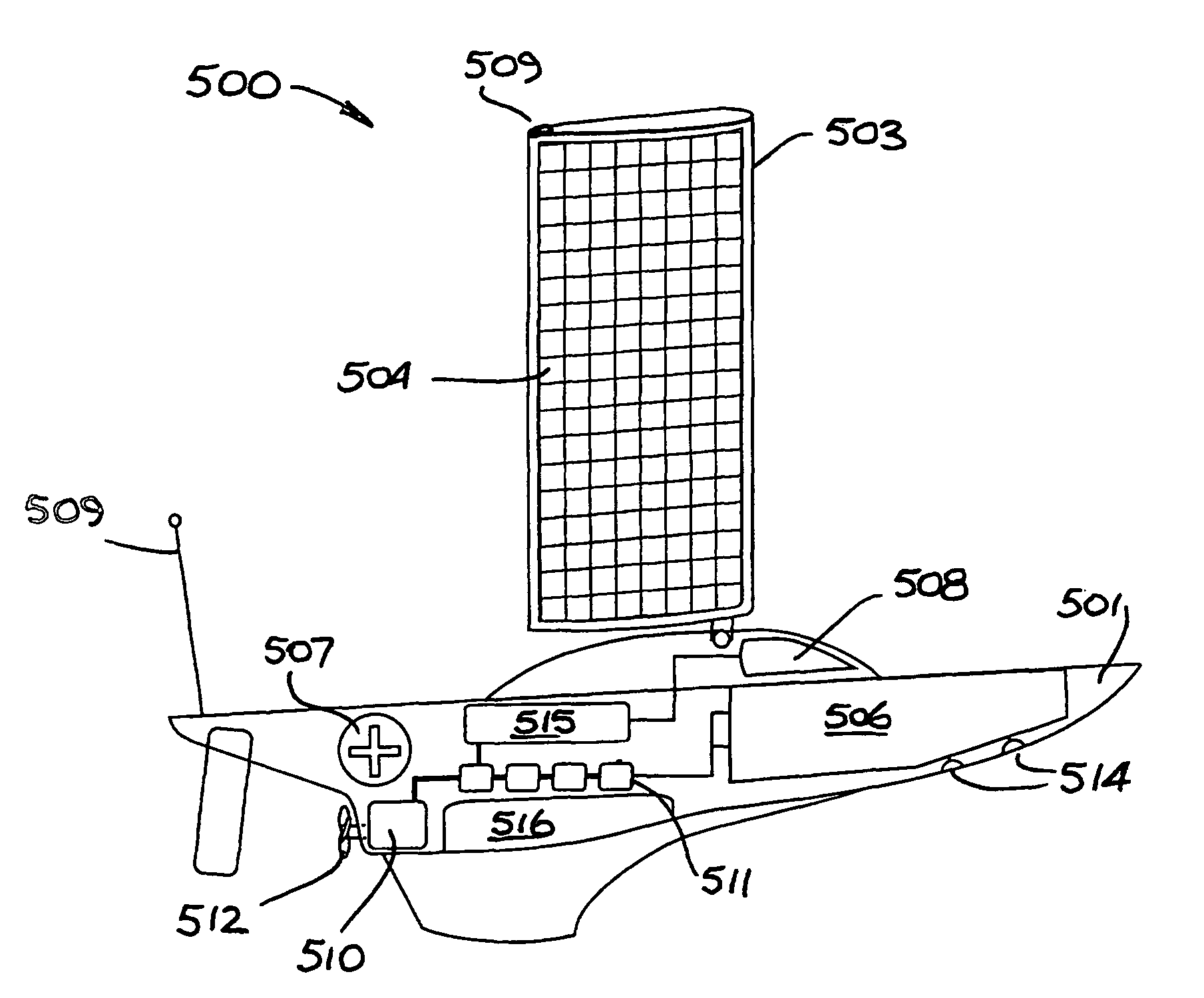
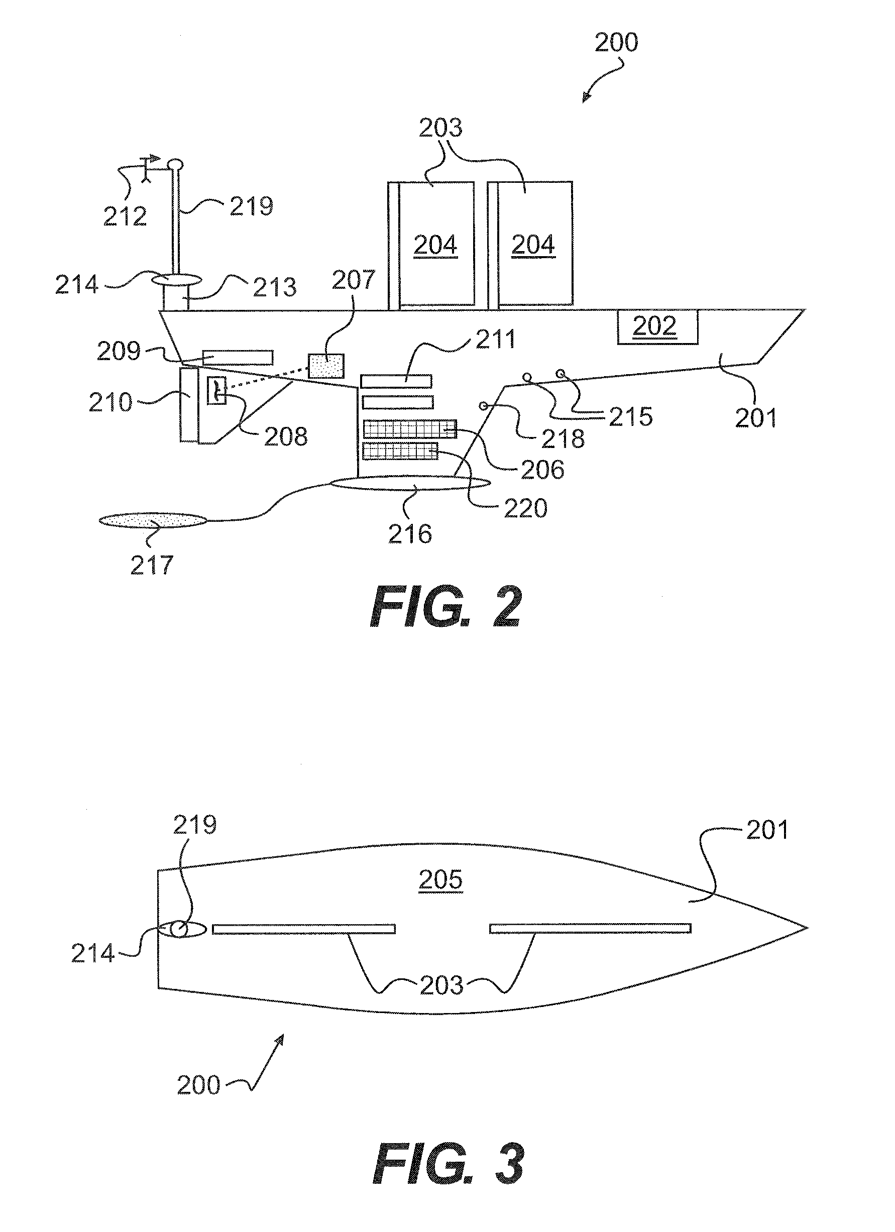
[0040]Turning to FIGS. 2 and 3 there is represented a UOV 200 of the invention which is able to be constructed at relatively low cost. The vehicle includes an enclosed hull 201 constructed of fiberglass material, having a length of 3 to 15 meters (10-50 feet), a beam of about 1 to 10 meters (3-35 feet) and weighing in the region of 100 to 8000 kg (220 to 17600 pounds). The hull encloses a payload compartment 202 for a payload weighing in the region of 50 to 500 kg (110 to 11000 pounds). Hull extensions including a keel and a rudder (not shown)are retractable to facilitate storage and handling.

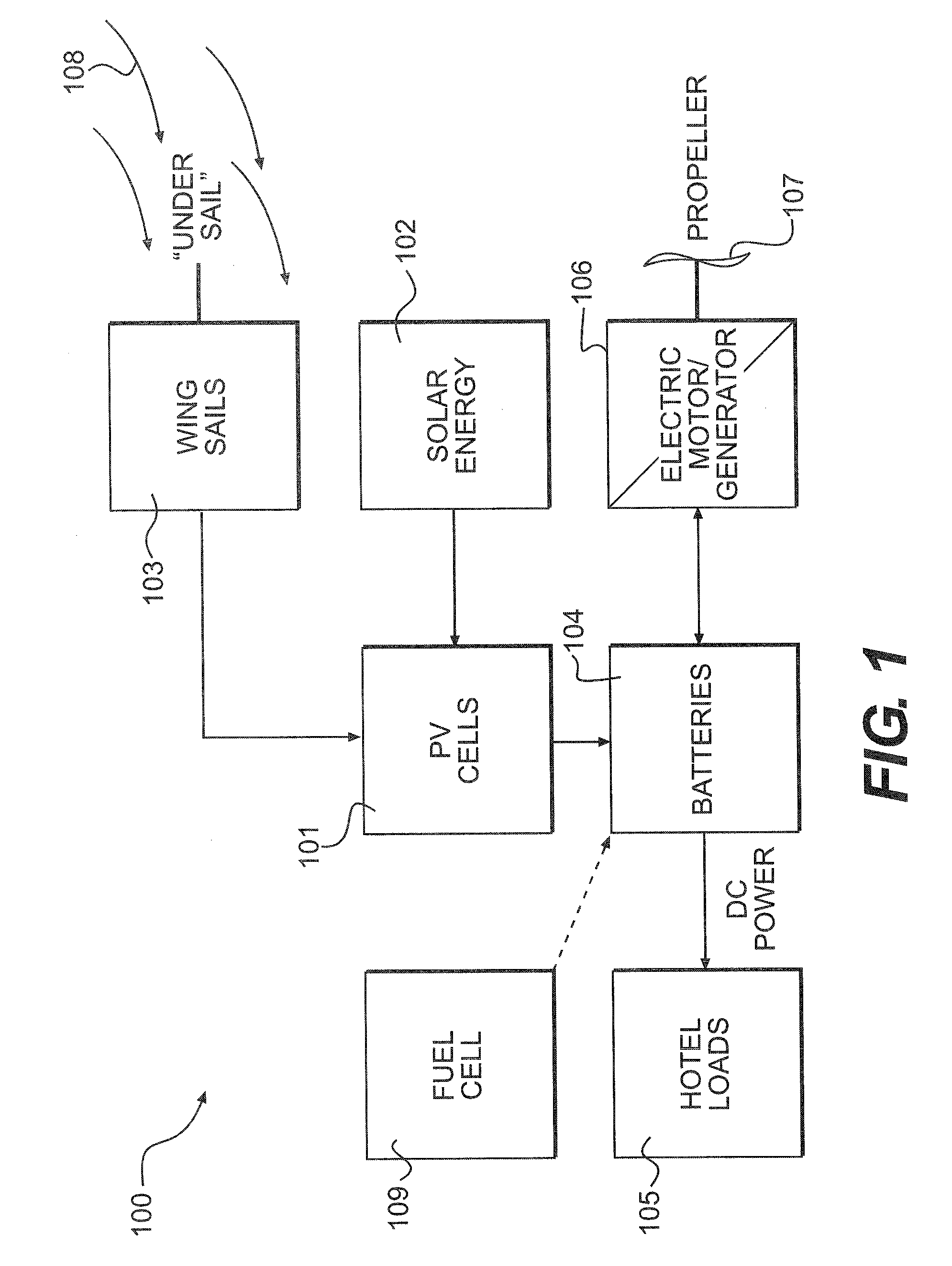
[0041]The UOV includes a hybrid propulsion system having two retracting wing sails 203 are attached to the hull 201 for collecting wind energy to propel the vehicle. Both the surface of the sails 204 and the upper surface of the hull or deck 205 include sections covered with photovoltaic cells. The photovoltaic cells convert ambient solar energy into electrical energy for supply to a battery ba...

second embodiment

[0044]In FIGS. 4 to 6 there is depicted a UOV 300 of the invention suited to stealth, surveillance and additional roles requiring submersible or submerged vehicle operation. The enclosed hull 301 is constructed of a carbon fibre composite material and has the general appearance of an aquatic animal, here a dolphin or porpoise. Accordingly the hull has a length of 1 to 10 meters (3-30 feet), a width of about 0.1 to 3 meters (0.5-9 feet) and a weight of 50 to 500 kg (110 to 1100 pounds). The enclosed hull 301 includes in internal payload bay 302 for accommodating a payload weight of 10 to 100 kg (22 to 220 pounds).

[0045]The UOV includes a hybrid propulsion system including an electric motor 303, a fuel cell 304, electrical storage cells such as a battery bank 305 and a photovoltaic array 306 for collecting solar energy. The PV array 306 is provided on the surface of a wing sail 308 which is attached to the hull 301. It is anticipated that a 1 m2 wing sail operating in a 18 knot trade ...

third embodiment

[0048]Turning to FIGS. 7 and 8, there is depicted a UOV 400 of the invention which is suited to higher speed delivery of a larger capacity payload. The vehicle has a hull assembly, which includes a central hull 401 and two floats 402 with respective outriggers 403, constructed of a composite material having an overall length of 8 to 20 meters (25-65 feet), a beam of 6 to 16 meters (20 to 50 feet) and a weight of 400 to 8000 kg (880-17600 pounds). A pair of wing sails 404 having photovoltaic cells 405 disposed thereon is provided on the central hull 401 to capture both wind and solar energy. Each wing sail 404 is attached to the hull such that it may be declined along or laterally of the hull assembly when not required for wind propulsion purposes. The declined position of the wing sails reduces the silhouette of the vehicle whilst optionally allowing collection of solar energy. Further photovoltaic cells 406 are mounted between the outriggers 403 to enhance the surface area availabl...


PUM


Abstract

An unmanned, autonomous, waterborne vehicle (500) for marine use capable of operating on and below the surface of water, said vehicle (500) including an enclosed hull (501) having a payload bay (506), a hybrid propulsion system having energy collection means (504) in the form of a wing sail (503) covered with photovoltaic cells and energy storage means (511) for utilizing at least solar energy and wind energy, a plurality of sensors (508, 514) for detecting predetermined environmental parameters and a communications system (509, 515) for transmitting data from said sensors (508, 515) to and for receiving command signals from one or more remote stations and / or cooperating vehicles.

Description

[0001]This application claims the benefit of the filing of International Application No. PCT / AU2004 / 001014, filed Jul. 30, 2004; which in turn claims the benefit of Australian Patent Application Nos. 2003903968 filed Jul. 31, 2003 and 2004902116 filed Apr. 21, 2004.BACKGROUND OF THE INVENTION[0002]1. Field of the Invention[0003]The present invention relates to unmanned, autonomous, waterborne vehicles for marine use, herein referred to as unmanned ocean vehicles (UOVs). In particular, although not exclusively, the invention relates to unmanned ocean vehicles utilising renewable energy sources which enable extended periods of operation, such as in remote ocean surface surveillance.[0004]2. Discussion of the Background Art[0005]The military, governmental and commercial uses for UOVs in warfare, exploration, research and monitoring applications at sea are numerous. The ability of conventional platforms, such as ships and buoys, to gather data and information in these applications is li...

Claims


Application Information

Patent Timeline
Patent Type & Authority Patents(United States)
IPC IPC(8): B63G8/00B63H23/00B63H21/17B63H19/00B63G8/22B63H9/00B60L11/00B63G8/08B63H23/24B60L8/00B63B35/00B63C11/42B63H9/06B63H21/20
CPCB63B35/00B63G8/001B63H9/0607B63H21/20B63B2035/006B63B2035/4453B63G2008/004B63H2021/171Y02T70/5236Y02T70/5245B63H9/061Y02T10/7072
Inventor DANE, ROBERT A.KILBOURN, EDWARD PAYNE
Owner SOLAR SAILOR PTY LTD
Why Eureka
Try Eureka