Steam turbine rotor, inverted fir-tree turbine blade, low pressure steam turbine with those rotors and blades, and steam turbine power plant with those turbines

a technology of inverted fir-tree turbine blades and steam turbines, which is applied in the direction of liquid fuel engines, vessel construction, marine propulsion, etc., can solve the problems of severe influence, and reduce shear stress in the rotor hook. , the effect of reducing the shear stress

Active Publication Date: 2010-09-14
MITSUBISHI POWER LTD
View PDF23 Cites 11 Cited by
  • Summary
  • Abstract
  • Description
  • Claims
  • Application Information

AI Technical Summary

Benefits of technology

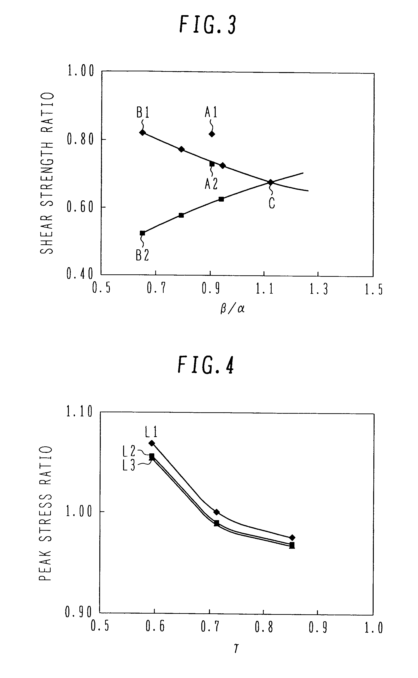
[0008]Accordingly, it is a very important problem to select a proper shape while achieving balance among those stresses, and to reduce stress in the turbine rotor corresponding to a material strength ratio between the blade material and the rotor material.
[0010]An object of the present invention is to, in a turbine rotor in which a rotor material has lower tensile strength than a blade material and the difference in tensile strength between both the materials is large, properly distribute a strength margin on the blade side to a strength margin on the rotor side with the aim of reducing shear stress in a rotor hook, increasing stiffness of the rotor hook, and reducing peak stress in a rotor neck, to thereby provide a steam turbine rotor and an inverted fir-tree turbine blade in which stress balance is made more appropriate depending on a material strength ratio of the blade material to the rotor material. Another object of the present invention is to provide a low-pressure steam turbine and a high-, intermediate- and low-pressure integral steam turbine which include those rotors and blades, as well as a steam turbine power plant with those turbines.
[0016]According to the present invention, in the turbine rotor in which the rotor material has lower tensile strength than the blade material and the difference in tensile strength between both the materials is large, a strength margin on the blade side is properly distributed to a strength margin on the rotor side with the aim of reducing shear stress in the rotor hook, increasing stiffness of the rotor hook, and reducing peak stress in the rotor neck, to thereby provide the steam turbine rotor and the turbine blade in which stress balance is made more appropriate depending on a material strength ratio of the blade material to the rotor material. Further, the present invention is able to provide the low-pressure steam turbine and the high-, intermediate- and low-pressure integral steam turbine which include those rotors and blades, as well as the steam turbine power plant with those turbines.

Problems solved by technology

If the rotor should be damaged, the resulting influence is severer than damage of the blade.
Accordingly, it is a very important problem to select a proper shape while achieving balance among those stresses, and to reduce stress in the turbine rotor corresponding to a material strength ratio between the blade material and the rotor material.

Method used


Image

  • Steam turbine rotor, inverted fir-tree turbine blade, low pressure steam turbine with those rotors and blades, and steam turbine power plant with those turbines
  • Steam turbine rotor, inverted fir-tree turbine blade, low pressure steam turbine with those rotors and blades, and steam turbine power plant with those turbines
  • Steam turbine rotor, inverted fir-tree turbine blade, low pressure steam turbine with those rotors and blades, and steam turbine power plant with those turbines

Examples


first embodiment

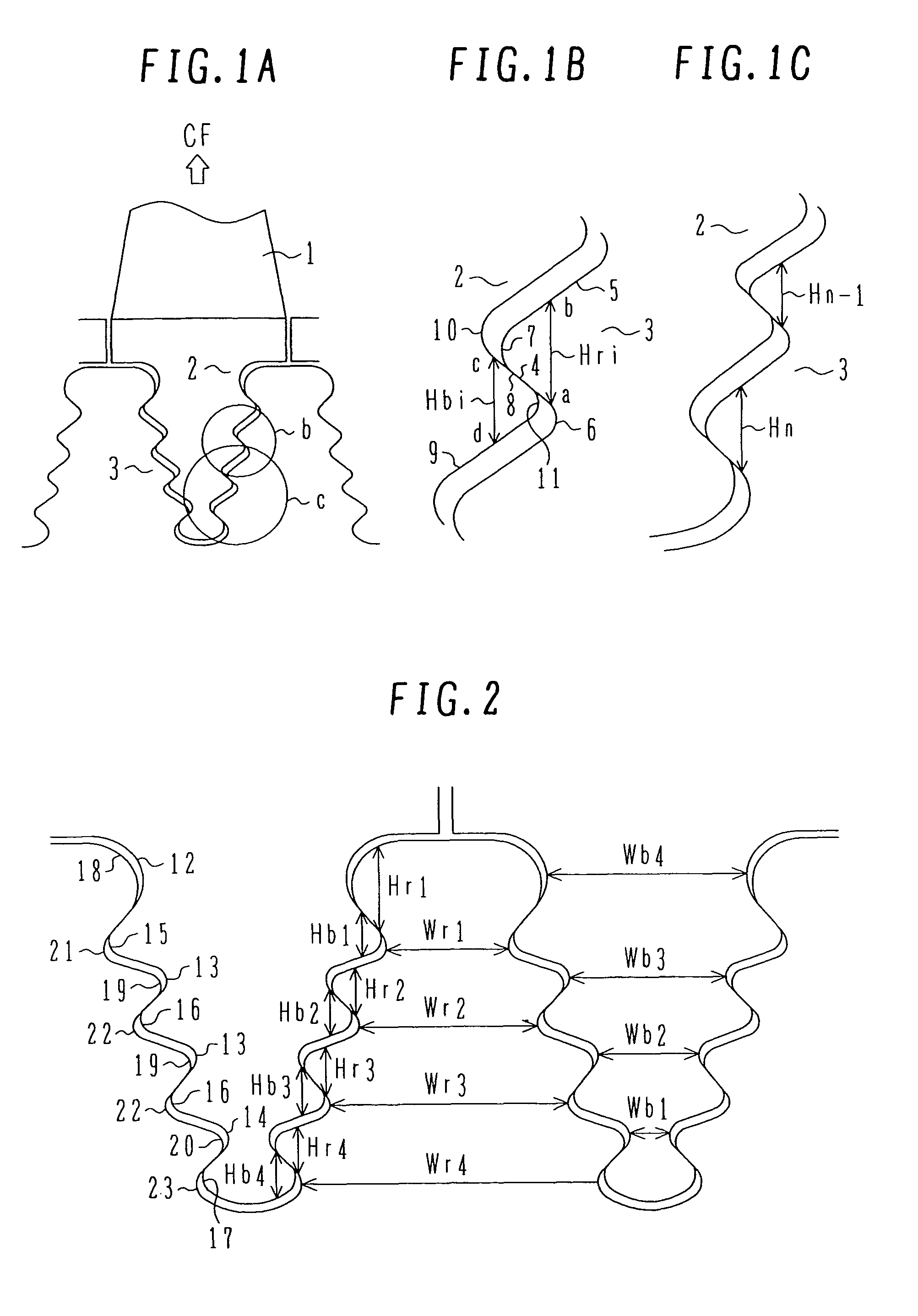
[0028]FIG. 1A is a partial cross-sectional view of a turbine rotor according to the present invention, FIG. 1B is an enlarged view of an area b in FIG. 1A, and FIG. 1C is an enlarged view of an area c in FIG. 1A. This first embodiment is related to a turbine rotor 3 in which the tensile strength of a blade material is 965-1325 MPa and the tensile strength of a rotor material is 825-945 MPa, namely the tensile strength of the blade material is 1.2-1.6 times that of the rotor material, and in which the turbine rotor has an attachment structure with respect to an inverted fir-tree blade root 2 extending from a turbine moving blade 1 in a direction toward the rotor center.

[0029]In the turbine rotor 3 having the attachment structure with respect to the turbine blade 1 having the inverted fir-tree blade root 2, four hooks are formed in each of the blade root and a rotor groove. The blade root is inserted in the axial direction of the turbine rotor such that the respective hooks of the bla...

second embodiment

[0051]FIG. 7 is an enlarged cross-sectional view of principal parts of the turbine rotor according to the present invention. The hook of the turbine rotor 3 is shaped such that the hook contact surface 4 and the hook non-contact surface 5, shown in FIG. 1, are interconnected by a flat surface 24 and inscribed circular surfaces 25 and 26 formed on both sides of the flat surface 24. With such a structure, the circumferential-direction size of the turbine rotor hook can be reduced in comparison with the hook of the first embodiment in which the hook contact surface 4 and the hook non-contact surface 5 are interconnected by one inscribed circular surface 7. Therefore, the tensile stress in the blade neck can be reduced and workability can be increased. Though not shown in FIG. 7, the turbine blade 1 is also preferably formed such that surfaces corresponding to the hook contact surface 4 and the hook non-contact surface 5 are interconnected by surfaces similar to the flat surface 24 and ...

third embodiment

[0054]FIGS. 8A and 8B show a long blade for 3000 rpm, which has an airfoil height of 48″ (inches) and is used as the last stage blade of a low-pressure steam turbine according to the present invention. Specifically, FIG. 8A is a front view and FIG. 8B is a side view. As shown in FIG. 8, a blade root 52 is in the form of an inverted fir tree and has four stages of straight hooks on each of opposite sides of the blade root 52. Such blade hooks and blade necks have the same structure as that in the first or second embodiment. The blade root having those blade hooks and necks are attached respectively to corresponding rotor hooks and necks. An airfoil 51 has a thickness that is at maximum in the root and is gradually reduced toward its tip.

[0055]The last-stage blade in this third embodiment is made of steel which contains 0.15-0.40% by weight of C, 0.5% or less of Si, 1.5% or less of Mn, 2.0-3.5% of Ni, 8-13% of Cr, 1.5-4.0% of Mo, 0.05-0.35% of V, 0.04-0.15% of N, and, as required, 0.0...


PUM


Abstract

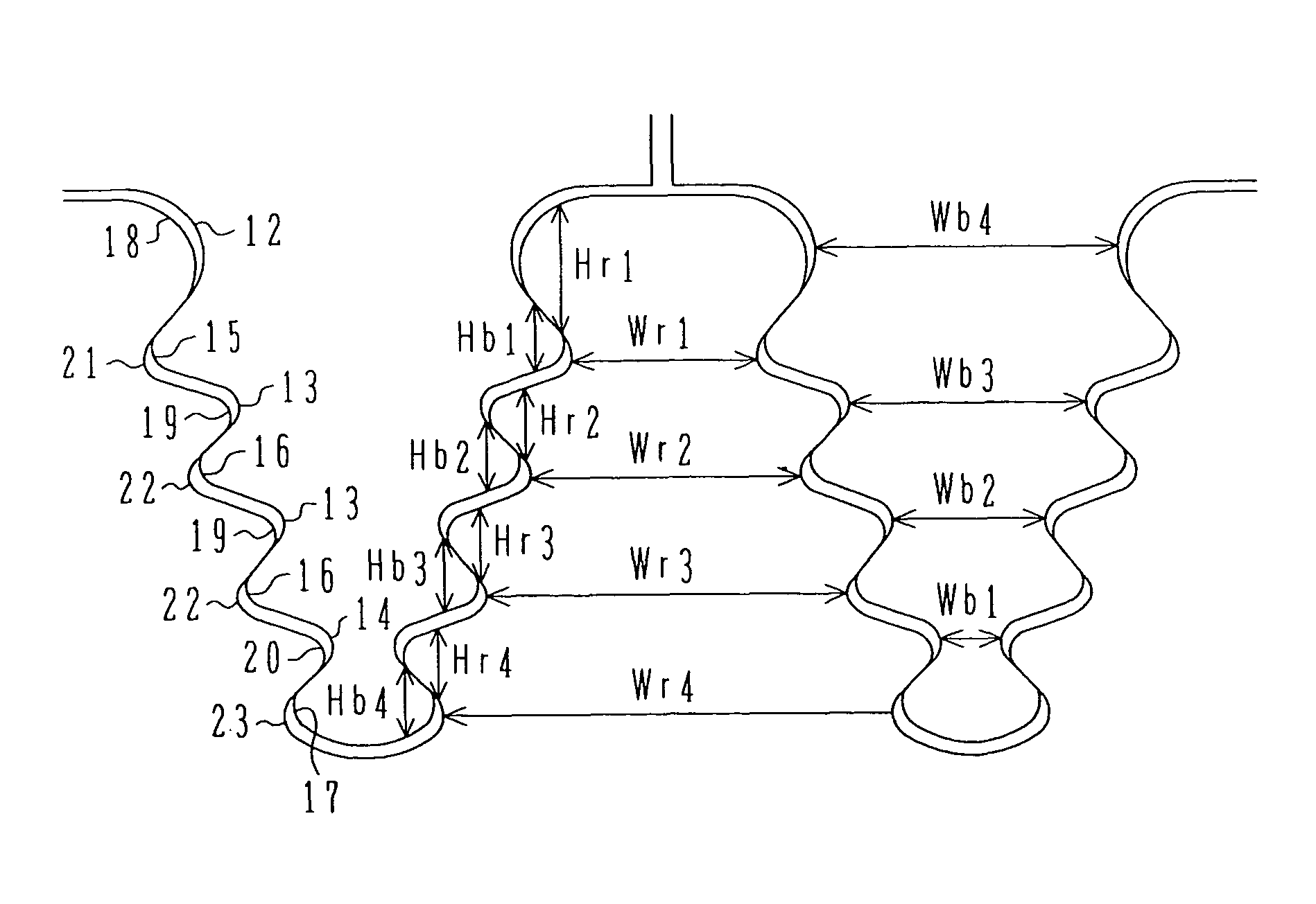
In a turbine rotor, a rotor radial-direction hook length (Hri) of an i-th rotor hook counting from the outermost circumference of the rotor and a blade radial-direction hook length (Hbi) of an i-th blade hook counting from the outermost circumference of the blade are set to satisfy the relationship of (Hri>Hbi). In the turbine blade, a rotor circumference-direction neck width (Wri) of an i-th rotor neck counting from the outermost circumference of the rotor and a blade circumference-direction neck width (Wbi) of an i-th blade neck counting from the innermost circumference of the blade are set to satisfy the relationship of (Wri>Wbi).

Description

BACKGROUND OF THE INVENTION[0001]1. Field of the Invention[0002]The present invention relates to a novel steam turbine rotor having an attachment structure with respect to an inverted fir-tree blade root which is inserted in the axial direction, and to a novel inverted fir-tree turbine blade. The present invention also relates to a low-pressure steam turbine with those rotors and blades, and to a steam turbine power plant with those turbines.[0003]2. Description of the Related Art[0004]From the viewpoint of realizing higher capacity and higher efficiency of a steam turbine, one of the most important themes is to obtain a longer blade in the last stage of a low-pressure steam turbine. To be adapted for a centrifugal force increased with the longer blade in the last stage of the low-pressure steam turbine, design has been generally conducted aiming to increase the material strength. However, a rotor material, in particular, has higher sensitivity to stress corrosion cracking (SCC) wit...

Claims


Application Information

Patent Timeline
Patent Type & Authority Patents(United States)
IPC IPC(8): F01D5/30
CPCF01D5/06F01D5/3007F05D2220/31F05D2250/70F01D5/16F01D5/30
Inventor SUZUKI, FUMIYUKIASAI, KUNIOKUDO, TAKESHINAKAMURA, TATEKI
Owner MITSUBISHI POWER LTD
Why Eureka
Try Eureka