
Implantable central venous injection port and external needle guide

Inactive Publication Date: 2010-09-14
CHUTER TIMOTHY A M +1
View PDF6 Cites 34 Cited by
  • Summary
  • Abstract
  • Description
  • Claims
  • Application Information

AI Technical Summary

Benefits of technology

[0007]In one embodiment of the present invention, the invention is directed to an assembly for subcutaneous injections comprising an implantable injection port comprising a body with a plenum, and a top side and bottom side; an elastomeric self-sealing diaphragm sealed to the body over the plenum, the body having an outlet port connecting the plenum to a central venous catheter, and one or more ferromagnetic compatible elements positioned about the elastomeric self-sealing diaphra

Problems solved by technology

However, needle puncture of the injection port is not necessarily easy or secure.
In obese patients, the location or position of a port implanted close to the skin surface is frequently unstable because the implant is within the subcutaneous fat.
If the injection port is placed in a more stable location in an obese patient, such as on the pectoral fascia, the port is then positioned far from the skin surface, making a successful injection of the port more difficult.
In either situation, there is a risk of accidental subcutaneous infiltration of the agents because of the needle missing the injection port.
Subcutaneous infiltration of chemotherapeutics, which are very toxic, can cause severe inflammation and necrosis of tissue.
This can lead to severe complications and is especially detrimental to patients that are already debilitated and / or in fragile condition.
Even when the needle tip position has been established by blood withdrawal prior to penetration of the injection port, there is no guarantee that the needle will stay in position within the port for the duration of the infusion of a chemotherapy agent and / or other medicinal agent.

Method used


Image

  • Implantable central venous injection port and external needle guide
  • Implantable central venous injection port and external needle guide
  • Implantable central venous injection port and external needle guide

Examples


Embodiment Construction

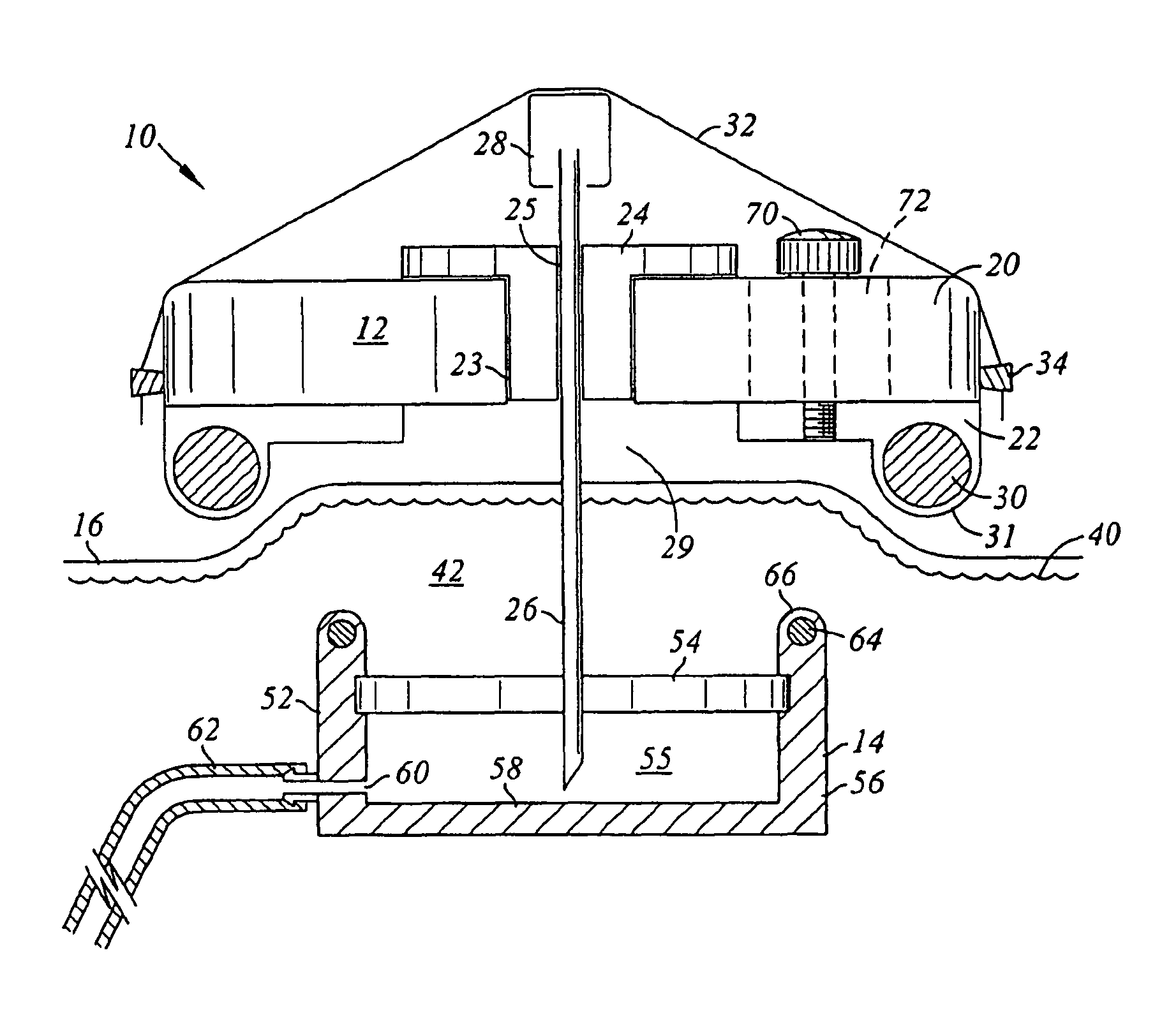
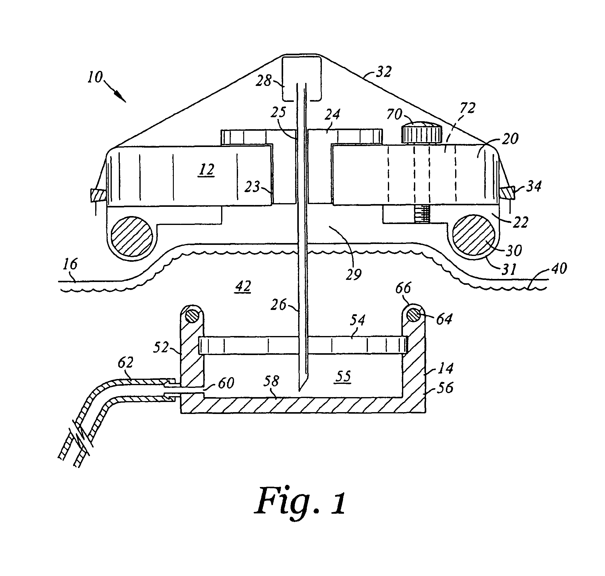
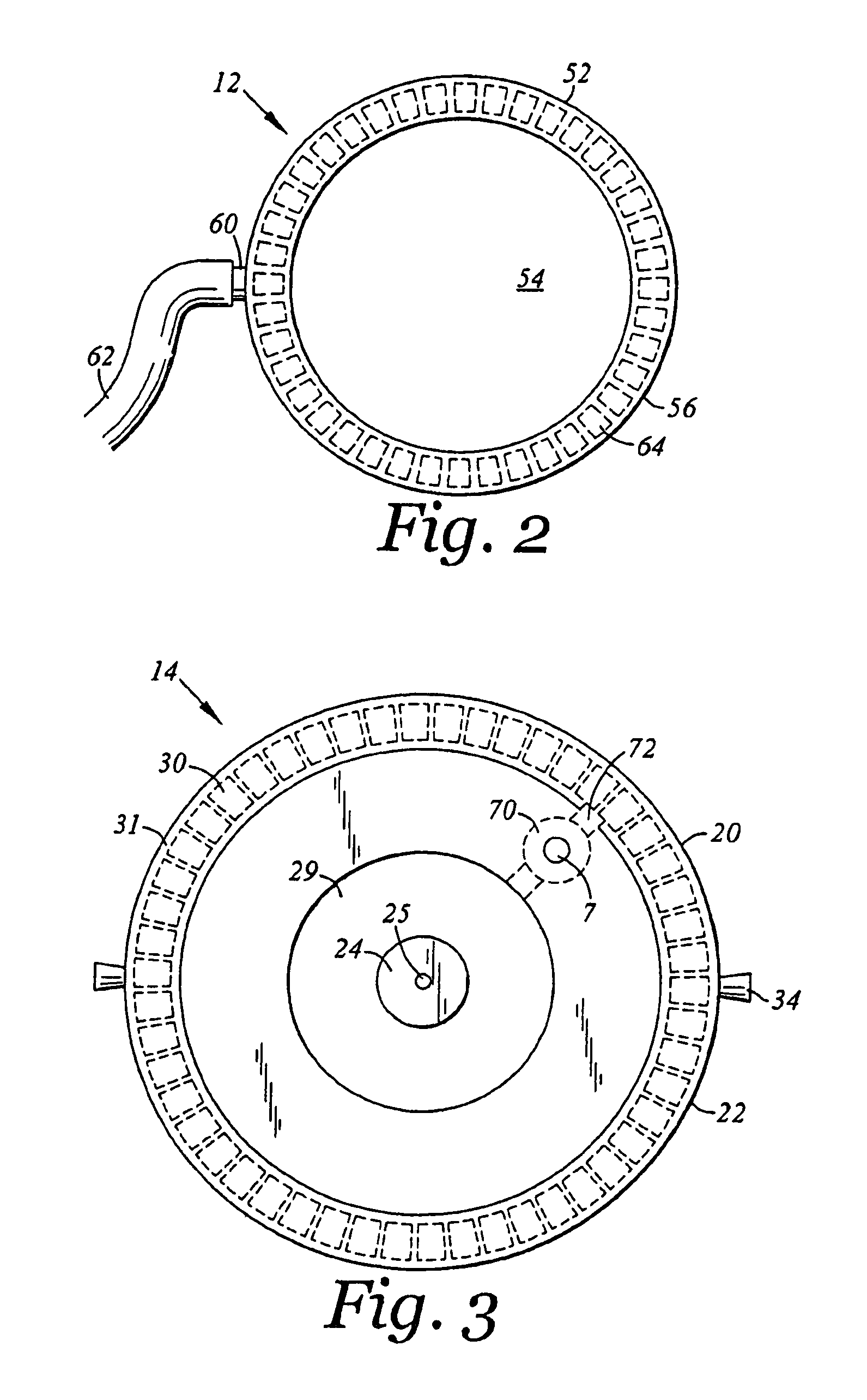
[0025]Referring to FIGS. 1-3, the needle guide and port assembly 10 of the present invention is shown in use on a patient. The invention comprises an external needle guide and support 12 which is used on the exterior surface of a patient and a subcutaneous injection port 14 which is implanted into the patient and connected to a central venous catheter 62. FIG. 1 is not to scale and shows the assembly in an enlarged view. The external needle guide and support platform 12 comprises a body 20 and an attachment base 22. The body has a central bore 23 in which is inserted a sterile needle guide 24. The needle guide 24 has a central bore 25 which extends the length of it and is adapted to receive a hypodermic needle 26. Preferably the needle bore 25 receives the hypodermic needle 26 in a close relationship similar to a friction fit to properly align the needle and to prevent the needle from freely moving up or down within the needle bore. The hypodermic needle has a connector 28 at one en...


PUM


Abstract

An assembly for subcutaneous injections comprising an implantable injection port comprising a body with a plenum, an elastomeric self-sealing diaphragm sealed to the body or with a plenum, an outlet connecting the plenum to a conduit, and one or more ferromagnetic compatible elements positioned about the elastomeric self-sealing diaphragm and near the top side; and a needle support platform comprising a body having a top side and bottom side, with a needle guide extending from the top side to the bottom side, a needle secure; and an attachment base with a top side and bottom side, a center hollow open to the top and bottom sides, and one or more ferromagnetic compatible elements positioned about the center hollow and near the bottom side of the attachment base, the bottom side of the body of the needle support platform resting on the top side of the attachment base and slidable thereon, the position of the body on the attachment base adapted to be detachably secured.

Description

[0001]This application is continuation of U.S. patent application Ser. No. 11 / 072,778, filed on Mar. 3, 2005 now abandoned, and claims the benefit of U.S. Provisional Application No. 60 / 550,565, filed on Mar. 5, 2004.FIELD OF THE INVENTION[0002]The present invention is directed to an implantable injection port for a central venous catheter and to an assembly including the implantable injection port and an external needle guide and support.BACKGROUND OF THE INVENTION[0003]Implantable central venous catheters have been in use for several years and have many advantages for long-term venous access, particularly in cancer patients requiring chemotherapy and / or continuous doses of painkillers. The central location of the catheter tip in a high flow volume vein, such as a return vein to the heart, allows chemotherapeutic agents, which are toxic, to be quickly diluted by the high blood flow through the vein, minimizing local tissue damage and inflammation from the injected medicinal agent. ...

Claims


Application Information

Patent Timeline
IPC IPC(8): A61K9/22
CPCA61M39/0208A61M39/04A61M2039/0238
Inventor CHUTER, TIMOTHY A. M.MAA, JOHN
Owner CHUTER TIMOTHY A M
Learn More