Low-light viewing device for displaying image based on visible and near infrared light

a low-light viewing device and near infrared light technology, applied in the field of optical devices, can solve the problems of poor quality and/or limited user capabilities, low-light viewing devices for image intensification that are neither affordable nor easily adaptable to non-military uses, and the current generation of low-light viewing devices is not affordable and easy to adapt to non-military us

Inactive Publication Date: 2010-09-14
XENONICS INC
View PDF33 Cites 58 Cited by
  • Summary
  • Abstract
  • Description
  • Claims
  • Application Information

AI Technical Summary

Benefits of technology

[0016]The assembly of the present invention further provides for still image and / or video capture of an object viewed by the assembly by means of a simple control mechanism or switch operatively coupled to the camera assembly and to the signal processor for capturing and processing the image data for storage and retrieval. Memory sufficient to store such image data is included within the assembly, and a mechanism is provided for downloading the stored or captured image data to a remote device (e.g. a printer, computer or other peripheral device), such as a USB port or other interface. The digital low-light viewing assembly of the present invention further includes software and / or hardware functionality for implementing control program functions and enabling user selection of certain program mode features associated with the low-light assembly.

Problems solved by technology

However, many of the present low-light viewing devices currently being manufactured are neither affordable nor easily adapted to non-military uses.
In recent years a number of low-light viewing devices have been introduced into the consumer market, but are often of poor quality and / or offer the user limited capabilities.
Image intensified low-light viewing devices tend to be very expensive and require sophisticated, heavy lenses to produce long range images.
Image intensified devices are also quite prone to damage if used in high-light situations.
This characteristic renders such products virtually useless in most urban areas.
Moreover, due to excessive cost, thermal imaging devices have not been widely accepted.
As the use of integral LEDs renders the devices active devices, i.e., providing IR illumination to assist in detection, the devices consume power quickly.
The aforementioned devices are deficient in several respects, precluding practical use in both commercial arenas and by the military and law enforcement agencies.
Such devices tend to be both heavy and fragile, are unable to withstand the shock of impact and wear and tear caused by regular military or law enforcement use, and are easily permeated by water or moisture that can render them inaccurate or even unusable.
These devices also tend to have relatively short ranges, are bulky, are not ergonomic in design, and lack simplified user controls.
Moreover, such devices can be quite costly, often requiring proprietary components and elaborate assembly techniques, making them impractical for widespread military or law enforcement use.

Method used


Image

  • Low-light viewing device for displaying image based on visible and near infrared light
  • Low-light viewing device for displaying image based on visible and near infrared light
  • Low-light viewing device for displaying image based on visible and near infrared light

Examples


Embodiment Construction

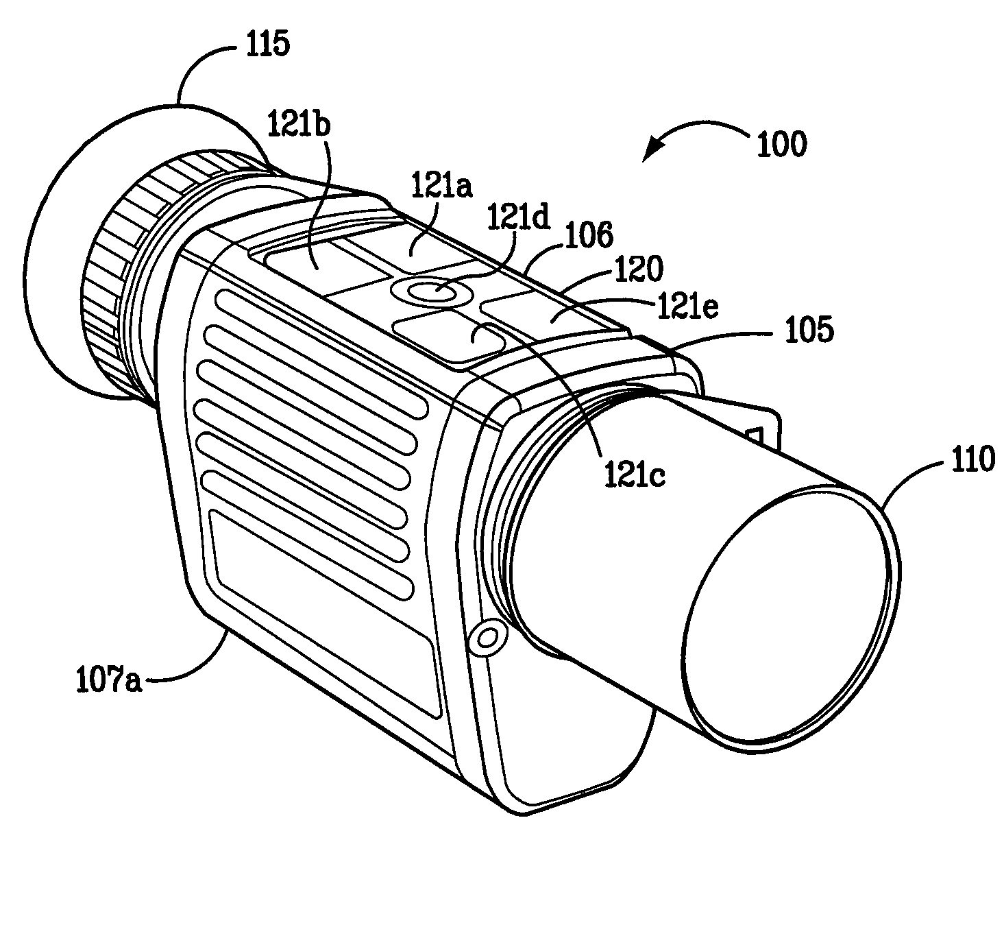
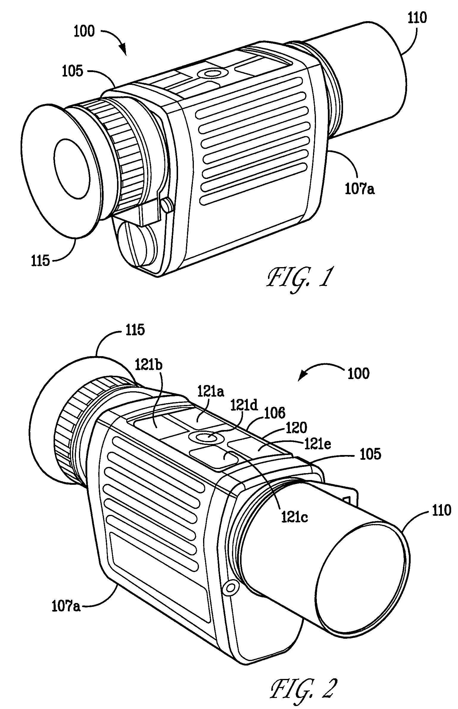
[0033]To address the problems of the prior art, an embodiment of the present invention provides a low-light viewing device capable of converting low-intensity visible light and infrared energy into a visible image. In an embodiment, the device is passive. In an embodiment, the device is ruggedized. In an embodiment, a digital low-light viewing assembly consistent with the present invention generally includes a sensitive digital camera having still / video image capture functionality, an LCD, OLED LCOS, CRT or plasma display having resolution greater than the resolution of the sensing device of the camera, a fixed focus lens with a low F-number, such as 1.0 or less, and a t-number of 1.5 or less, and control electronics as will be described in further detail below.

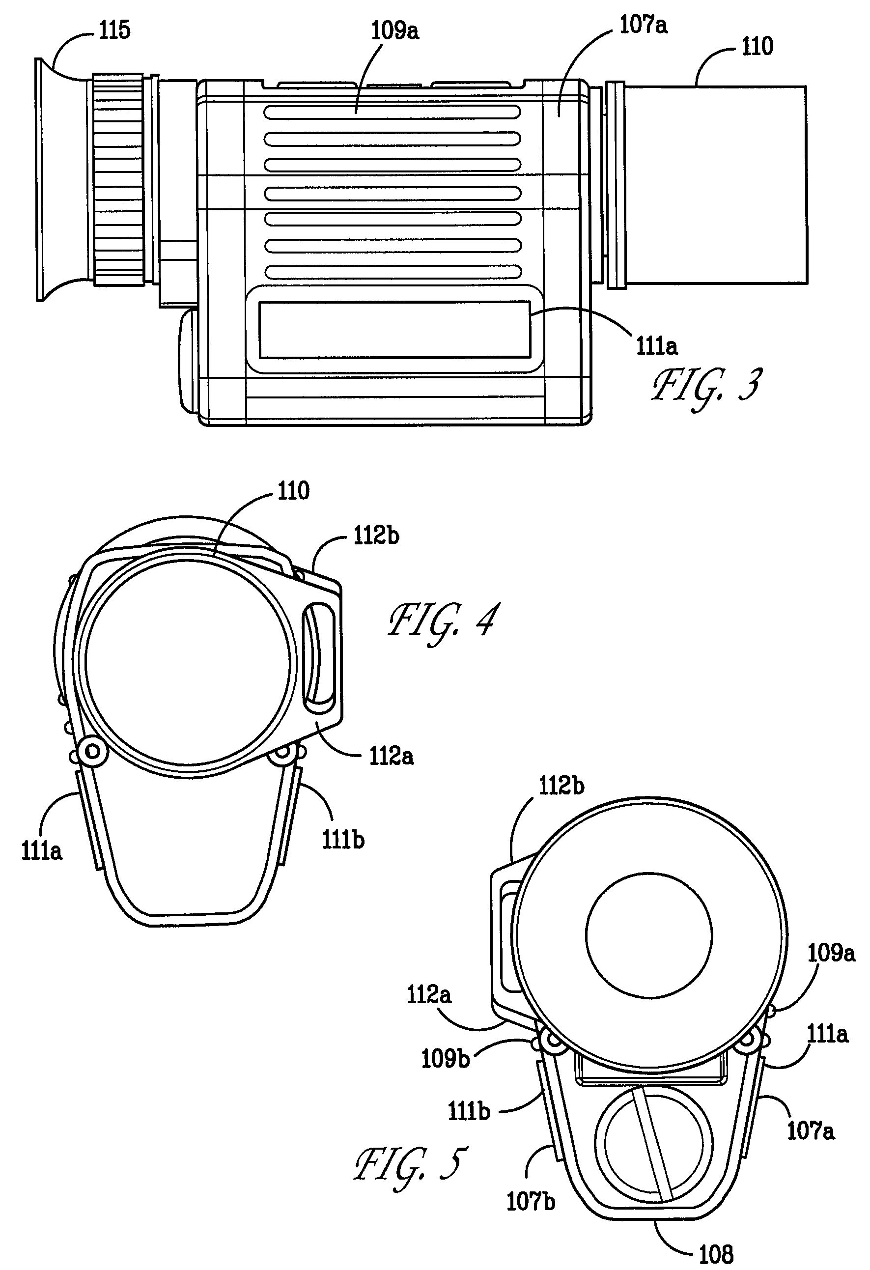
[0034]A disadvantage of prior art low light viewing devices is the loss of available light in lenses. For example, zoom lenses have an F number varying from about 1.6 to about 2.8 at highest magnification, resulting in loss o...


PUM


Abstract

A low-light viewing device includes a housing, having mounted thereto: a lens, an electronic camera for receiving light focused by the lens and for providing an output signal; a display for receiving the output signal and displaying an image detected by the camera; a controller for controlling the camera and the display, and a user interface for operating the controller. The lens may be a fixed focus lens having an F number of less than about 1, and a T number of less than about 1.5. The display may have a resolution at least as great as the resolution of the camera. The device may have a processor programmed to provide control signals to the camera and display depending on a selected light environment.

Description

RELATED APPLICATIONS[0001]This application claims the benefit of U.S. Provisional Patent Application No. 60 / 880,572, filed Jan. 16, 2007, which application is incorporated herein by reference in its entirety, and is a continuation-in-part of U.S. patent application Ser. No. 11 / 638,203, filed Dec. 13, 2006, now U.S. Pat. No. 7,420,153, which is a continuation of U.S. patent application Ser. No. 11 / 257,300, now U.S. Pat. No. 7,173,237, filed Oct. 24, 2005, which claims benefit of U.S. Provisional Patent Application No. 60 / 621,415, filed Oct. 22, 2004, and which is a continuation-in-part of U.S. patent application Ser. No. 11 / 060,903, filed Feb. 18, 2005, which claims benefit of U.S. Provisional Patent Application No. 60 / 546,812, filed Feb. 23, 2004, all of which applications are incorporated herein by reference in their entireties.FIELD OF THE INVENTION[0002]The present invention relates generally to optical devices that enable a viewer to detect, recognize, identify and observe objec...

Claims


Application Information

Patent Timeline
Patent Type & Authority Patents(United States)
IPC IPC(8): H01J40/14
CPCG02B23/12H04N5/33
Inventor KENNEDY, JEFFREYPALMER, GARY
Owner XENONICS INC
Why Eureka
Try Eureka