Method and system for navigating a catheter probe in the presence of field-influencing objects

a technology of field-influencing objects and navigation methods, which is applied in the direction of catheters, instruments, applications, etc., can solve problems such as large introduction errors

Inactive Publication Date: 2010-09-14
ENTERPRISE MEDICAL TECH +1
View PDF624 Cites 108 Cited by
  • Summary
  • Abstract
  • Description
  • Claims
  • Application Information

AI Technical Summary

Benefits of technology

[0066]Another aspect of the invention comprises a method of determining a substantially precise location of a field sensor within a navigational domain influenced by a field influencing shield device. The method includes sequentially projecting into the navigational domain, via three unidirectional coils and six delta coils, the navigational energy at a first frequency, and measuring a first signal value in the field sensor corresponding to each of the three unidirectional coils and the six delta coils, so as to produce nine of the first signal values. The method further includes forming three independent equations including three adjusted signal values corresponding to the unidirectional coils, three predetermined field magnitude values due to fields from each of the unidirectional coils and corresponding to the navigational energy at a last navigational point of the field sensor, the predetermined field magnitude values being manipulated so as to account for the shield device, and unknown orientation variables, and simultaneously solving the independent equations to determine the orientation variables corresponding to the compensated orientation of the sensing coil. The method also includes generating three lines and determining an intersection of the three lines, the intersection corresponding to the compensated position of the sensing coil. Each of the lines is generated from adjusted signal values corresponding to a pair of the delta coils, and predetermined field magnitude values due to the pair of delta coils and corresponding to the navigational energy at the last navigational point of the sensing coil while oriented according to the compensated orientation, the predetermined field magnitude values being manipulated so as to account for the effect of the shield device.

Problems solved by technology

Such objects respond to the known navigation field and introduce errors that can be large depending on the nature and relative position of the object.

Method used


Image

  • Method and system for navigating a catheter probe in the presence of field-influencing objects
  • Method and system for navigating a catheter probe in the presence of field-influencing objects
  • Method and system for navigating a catheter probe in the presence of field-influencing objects

Examples


Embodiment Construction

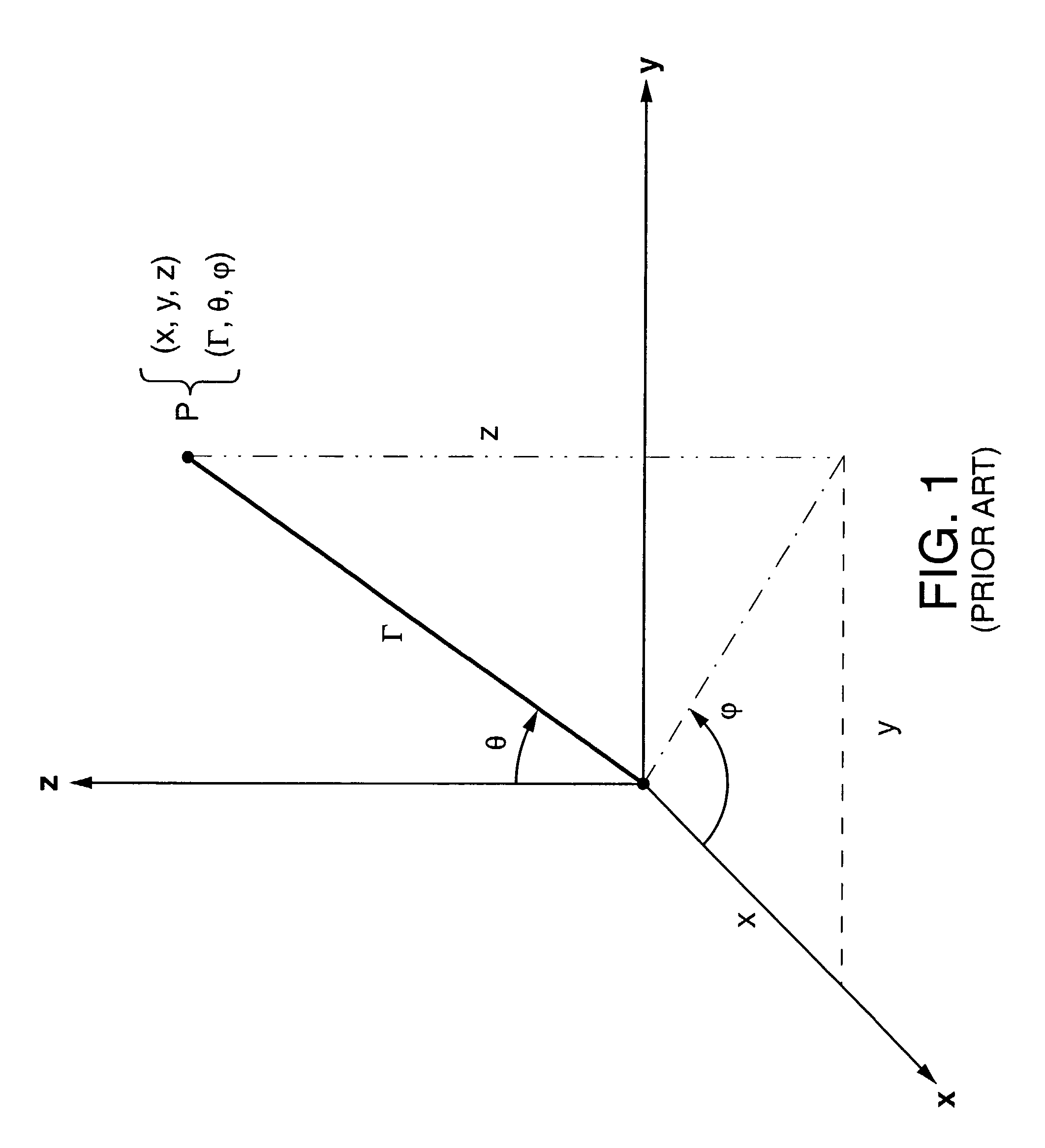
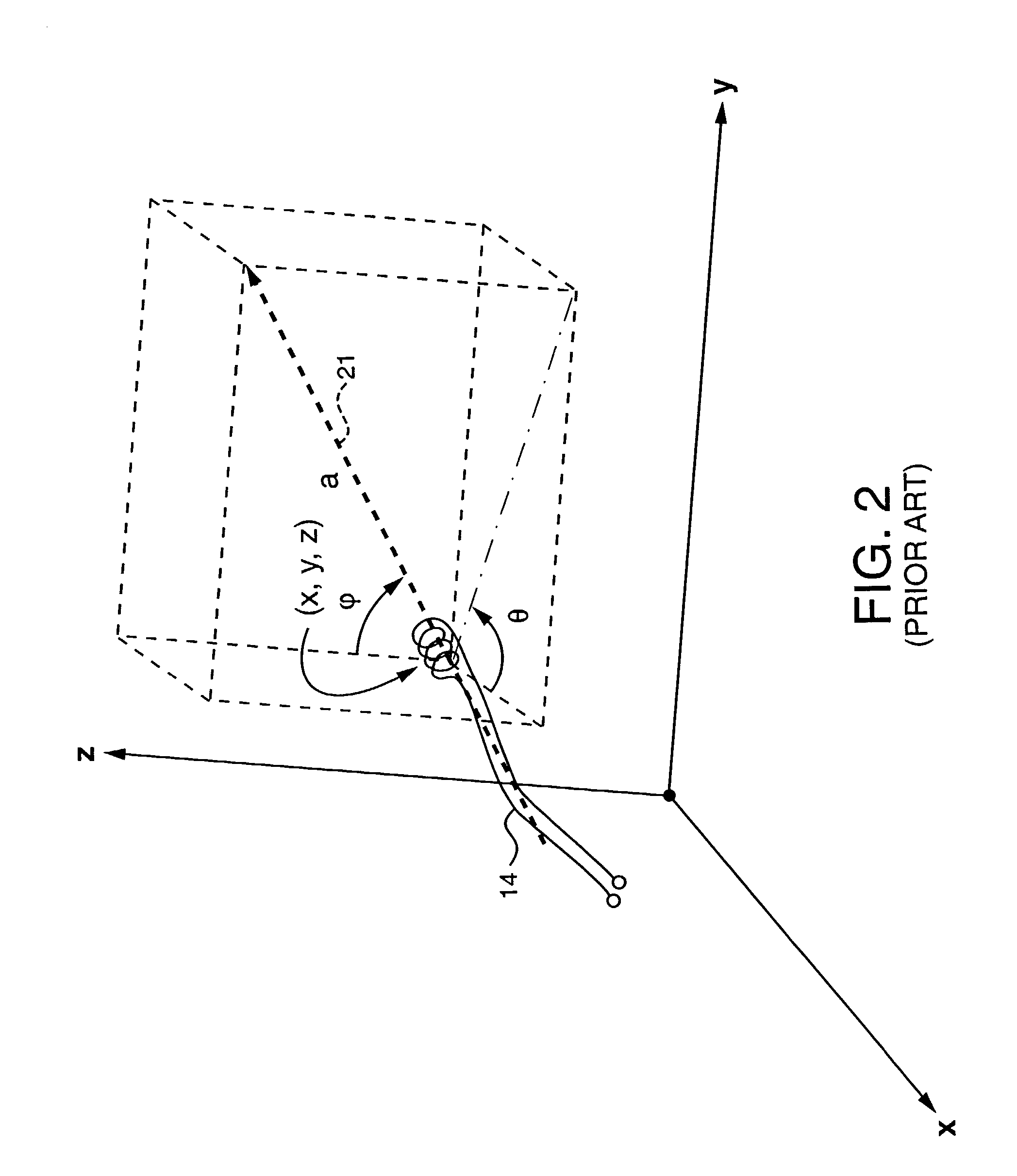
[0092]The present invention is directed to a system and method for determining the position and orientation of a catheter or other suitable probe inserted into a selected body cavity of a patient undergoing a surgical procedure in the presence of field-influencing objects.

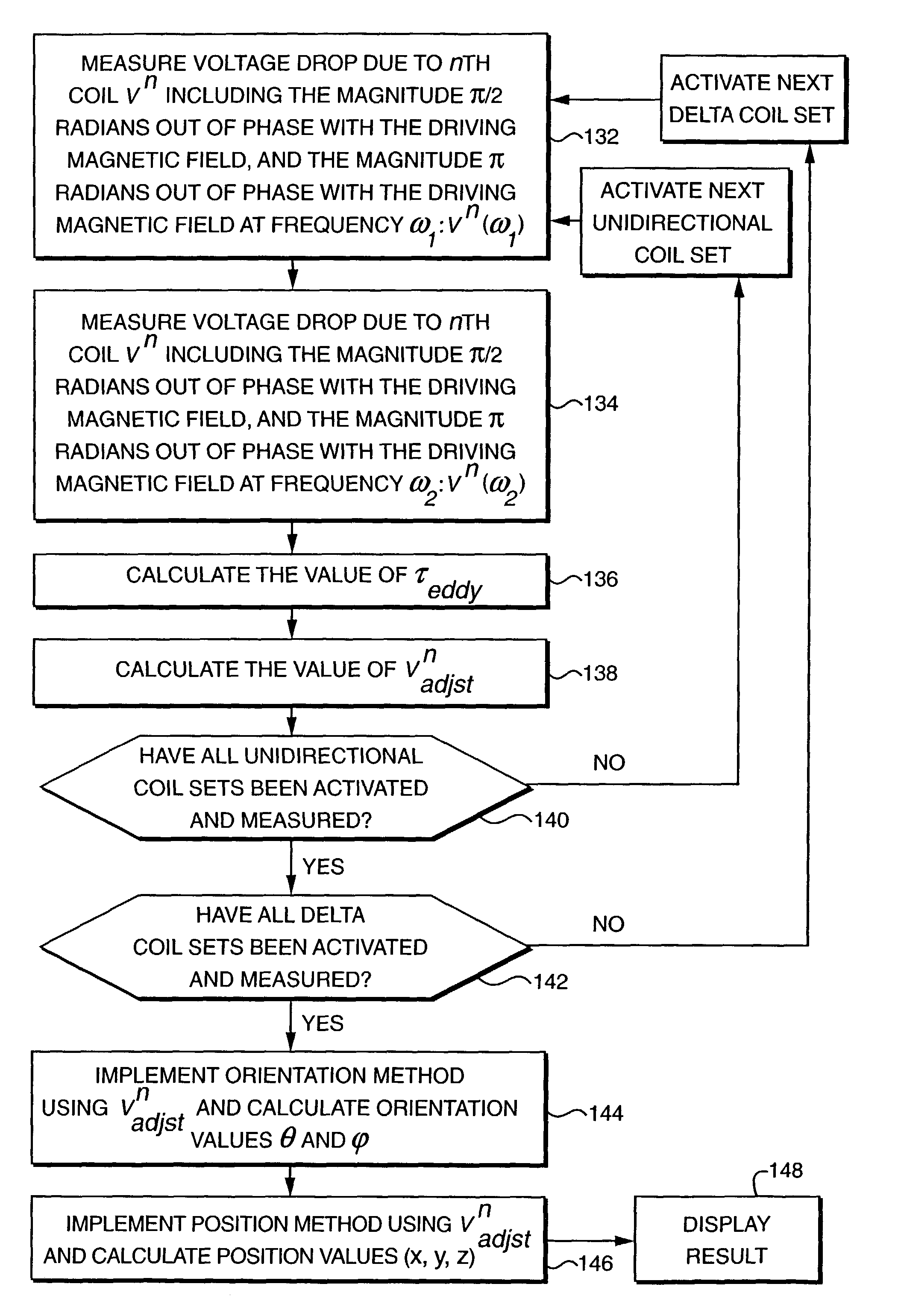
[0093]In one embodiment of the present invention, position and orientation data is determined from a series of measurements of voltage amplitudes induced within a sensing coil affixed to the distal end of the catheter probe as a result of the use of multiple waveforms. These voltage amplitudes, as a function of the waveforms, are induced in the sensing coil in response to known independent electromagnetic fields that are projected into the anatomical region of interest. The measurements provide information to compute the angular orientation and the positional coordinates of the sensing coil and account for the distortion of the known field by arbitrary conductors with field-induced eddy currents.

[0094]In another em...


PUM


Abstract

A system for and method of determining and compensating for the effect of a field influencing object on a field sensor, preferably a coil, that is within a navigational domain. The system includes a first and second transmitter to create signals. A signal processor is able to process the created signals. The method can include determining interference and/or a correct signal based on the two signals. Also, a shield can be provided to limit transmission of selected fields.

Description

CROSS-REFERENCE TO RELATED APPLICATIONS[0001]This application claims the benefit of United States Provisional Application No. 60 / 161,991, filed Oct. 28, 1999, the contents of which are incorporated herein by reference in their entirety, and from which priority is claimed.[0002]This application is a continuation of U.S. patent application Ser. No. 09 / 589,779, filed Jun. 8, 2000, now U.S. Pat. No. 6,493,573 the contents of which are incorporated herein by reference in their entirety, and from which priority is claimed.STATEMENT REGARDING FEDERALLY SPONSORED RESEARCH[0003]Not ApplicableREFERENCE TO MICROFICHE APPENDIX[0004]Not ApplicableCONCURRENTLY FILED APPLICATIONS[0005]The following United States patent applications, which were concurrently filed with this one on Oct. 28, 1999, are fully incorporated herein by reference: Patient-shielding and Coil System, by Michael Martinelli, Paul Kessman and Brad Jascob; Navigation Information Overlay onto Ultrasound Imagery, by Paul Kessman, Tr...

Claims


Application Information

Patent Timeline
Patent Type & Authority Patents(United States)
IPC IPC(8): A61B5/05A61B19/00A61M25/095
CPCA61B19/52A61B19/5244A61B19/22A61B2019/4081A61B2019/5251A61B2019/5272A61B2090/0481A61B90/36A61B2034/2072A61B34/20A61B34/70A61B2034/2051
Inventor MARTINELLI, MICHAEL A.KESSMAN, PAULJASCOB, BRAD
Owner ENTERPRISE MEDICAL TECH
Why Eureka
Try Eureka