Touch screen with relatively conductive grid

Inactive Publication Date: 2010-09-21
ELO TOUCH SOLUTIONS INC
View PDF17 Cites 36 Cited by
  • Summary
  • Abstract
  • Description
  • Claims
  • Application Information

AI Technical Summary

Benefits of technology

[0008]It is therefore a purpose of the invention to provide an improved touch screen allowing improved screen yield with inherent tolerance for individual and lot variances. It is a further object of the invention to permit simplified manufacture requirements for touch screens including less-demanding conductive-coating application; fewer

Problems solved by technology

However, with some electrode geometry (for example a spot electrode at each corner of a rectangle) equipotential pair measurements on some regions of the sensor cannot be uniquely mapped to Cartesian coordinate

Method used


Image

  • Touch screen with relatively conductive grid
  • Touch screen with relatively conductive grid
  • Touch screen with relatively conductive grid

Examples


Embodiment Construction

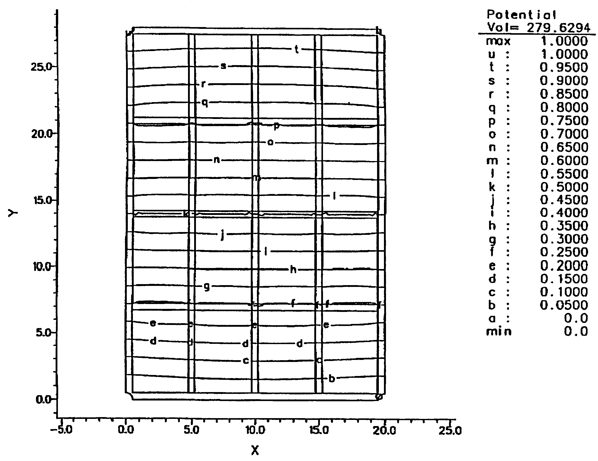
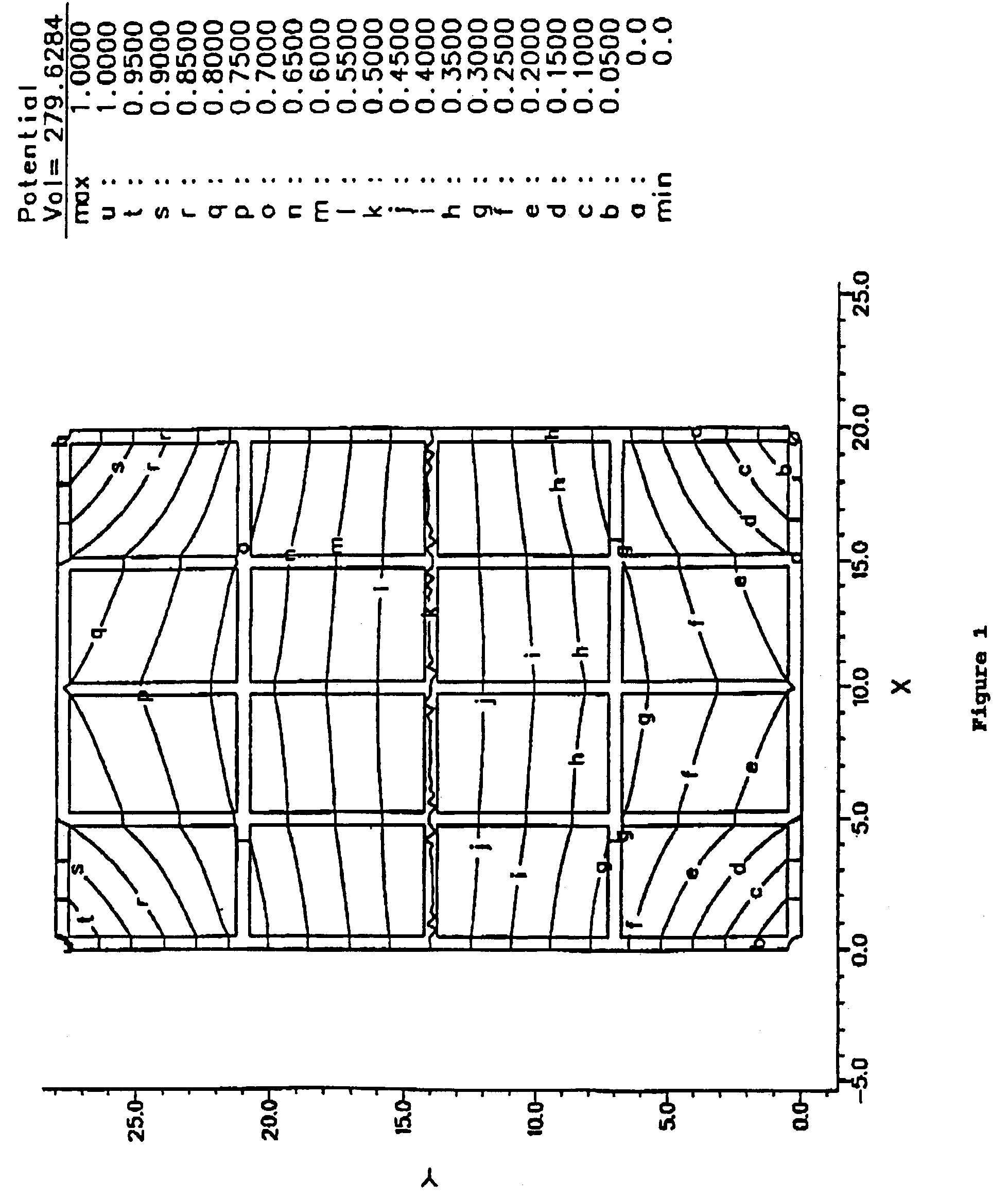
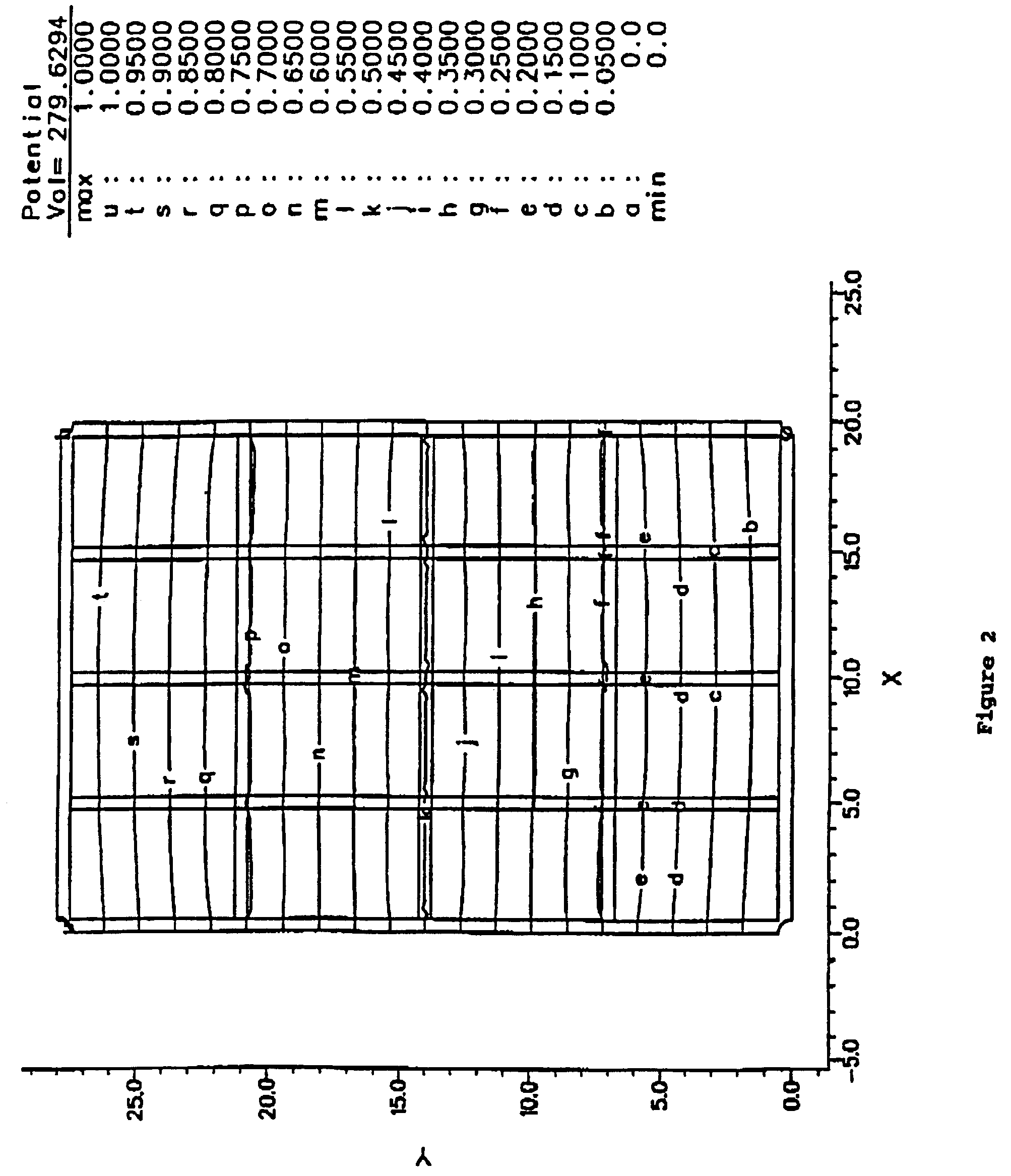
[0044]Computer simulations of the salient features of the grid invention have been made, with programs that solve boundary-value problems. Mathematical methods of solving equations of continuity coupled with a general relationship between current and electric field are used. These equations work for arbitrary conductivity and reduce to Laplace's equation for uniform conductivity. This general mathematical treatment leads to solutions for the equipotentials on conducting planes for any prescribed boundary conditions. For instance they can provide equipotential solutions for geometry where bordered frames are held at stationary electrical potentials, as in a resistance touch screen. As another example, solutions for the currents at the four corner electrodes when current is injected at a touch point in a rectangular sensor bounded by the bordered frame can be found. These so-called current injection methods have been used in physics research and for touch screen production for some ti...


PUM


Abstract

A new touch screen design provides for corrections of non-uniformities, more accurate touch point measurement, and multiple simultaneous touch point measurements through the use of a grid of relatively conductive lines.

Description

INTRODUCTION[0001]Since their introduction in the early 1970s, touch screens have afforded attractive alternatives to keyboards for certain computer applications. In many situations the keyboard and mouse are eliminated, because the touch screen provides the user with a much easier access to the computer. As a consequence, the market has grown to a substantial size, and a continued rapid growth is anticipated. However, current touch screens are difficult to produce, which creates a price barrier limiting growth into many new areas, such as education.[0002]In this disclosure, a new concept is discussed that virtually eliminates design constraints and provides more freedom for the configuration of touch screens. Examples are given to illustrate this new freedom in design parameters. These design concepts provide a basis for producing touch screens at a much lower cost, without sacrificing quality. Furthermore, the creation of new designs for special sensor size, shape, or electrical c...

Claims


Application Information

Patent Timeline
IPC IPC(8): G09G5/00G06F3/045G06F3/033G06F3/041G06F3/044
CPCG06F3/044G06F3/045G06F2203/04104
Inventor HURST, G. SAMUELRITCHIE, RUFUS H.BOULDIN, DONALD W.WARMACK, ROBERT J.
Owner ELO TOUCH SOLUTIONS INC
Why Eureka
Try Eureka