Polarization device to polarize and further control light

a polarization device and light control technology, applied in the direction of polarising elements, instruments, optics, etc., can solve the problems of unwanted astigmatism and valuable space, and achieve the effects of reducing ghost images, reducing back reflection, and conserving space in optical design

Inactive Publication Date: 2010-09-21
MOXTEK INC
View PDF472 Cites 30 Cited by
  • Summary
  • Abstract
  • Description
  • Claims
  • Application Information

AI Technical Summary

Benefits of technology

[0009]It has been recognized that it would be advantageous to develop a wire grid polarizer or polarizer device capable of reducing back reflection, and thus capable of reducing ghost images when used in an imaging system or display system. In addition, it has been recognized that it would be advantageous to develop a wire grid polarizer or polarizer device capable of polarizing and further controlling the light, such as the direction or modes of reflection. In addition, it has been recognized that it would be advantageous to develop a non-zero order type polarizer device capable of polarizing light while reflecting only light of non-zero order, and without reflecting light of the zero order. Furthermore, it has been recognized that it would be advantageous to develop an imaging system with such a wire grid polarizer or polarizer device capable of conserving space in the optical design, and capable of reducing ghost images and unwanted astigmatism.

Problems solved by technology

Tilting the polarizer, however, can take-up valuable space in a compact design, and can cause unwanted astigmatism.

Method used


Image

  • Polarization device to polarize and further control light
  • Polarization device to polarize and further control light
  • Polarization device to polarize and further control light

Examples


example 1

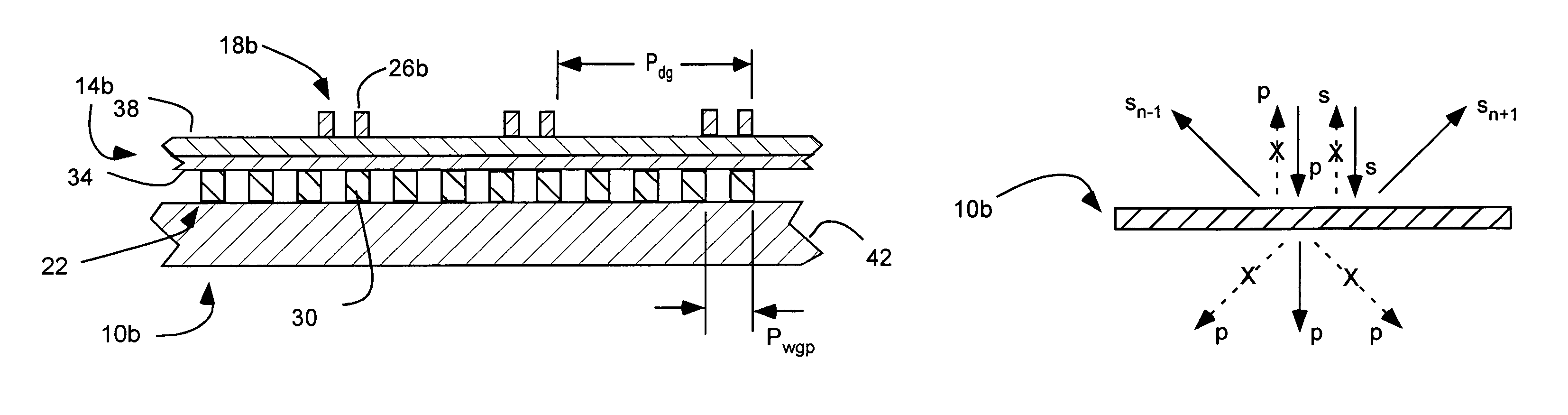
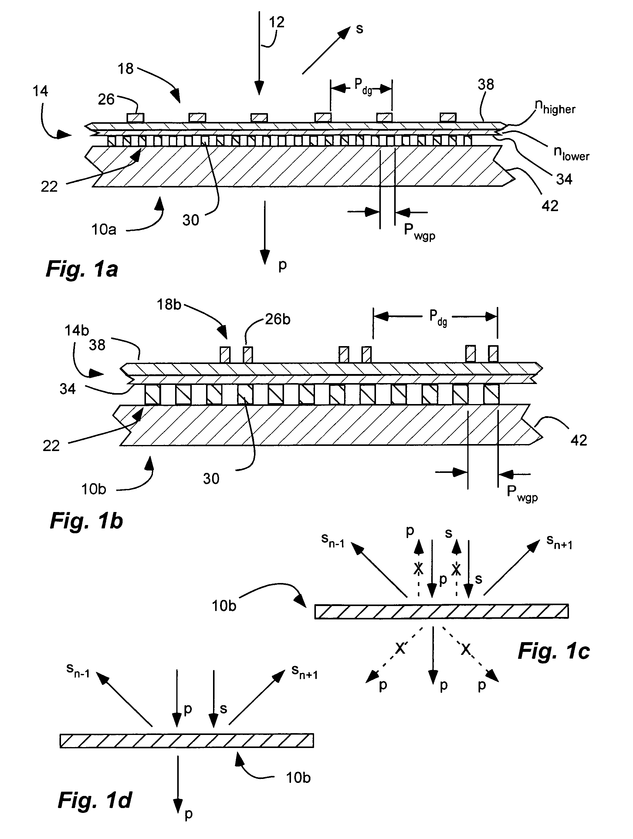
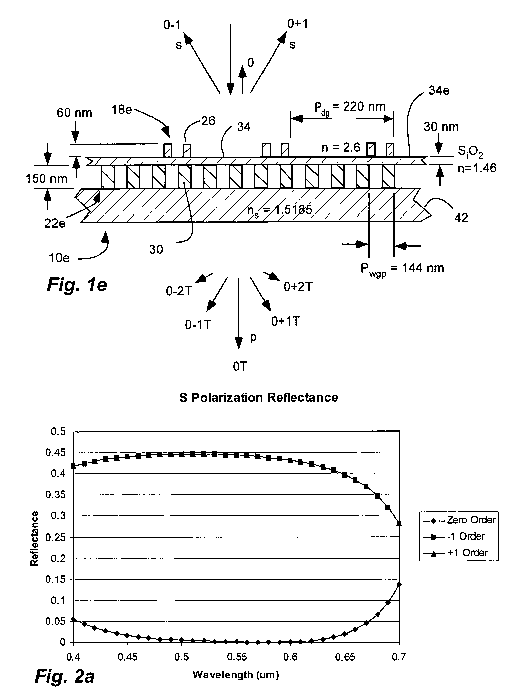
[0049]Referring to FIG. 1e, a first non-limiting example of a polarizer device 10e is shown. The polarizer device 10e includes a substrate 42 of BK7 glass (ns=1.5185). A wire grid polarizer 22e is disposed on the substrate. The wire grid polarizer 22e includes an array of elongated, parallel conductive wires 30 formed of aluminum, with a pitch or period Pwgp of 144 nm, a thickness of 150 nm, and a duty cycle (ratio of period to width) of 0.50 or width of 72 nm. A layer 34e of silicon dioxide (SiO2) (N=1.46) is disposed over the wire grid 22e. A diffraction grating 18e is disposed over the layer 34e. The diffraction grating 18e includes an array of elongated parallel dielectric ribs 26 with a period or pitch Pdg of 720 nm, a thickness of 60 nm, and an index of refraction of 2.6. The ribs of the diffraction grating are split, as shown. The present configuration is configured for non-zero order diffraction in reflection.

[0050]Table 1 shows the calculated performance of the polarization...


PUM


Abstract

A polarization device includes an optical stack with a diffraction grating and a wire grid polarizer with one disposed over the other. The wire grid polarizer includes an array of elongated, parallel conductive wires in accordance with PWGP<λ / 2 where PWGP is the period of the wires and λ is the wavelength of the light. The diffraction grating includes an array of elongated parallel dielectric ribs in accordance with PDG>λ / 2 where PDG is the period of the ribs.

Description

RELATED APPLICATIONS & PRIORITY CLAIM[0001]This is a continuation-in-part of U.S. patent application Ser. No. 11 / 005,927 filed Dec. 6, 2004, now U.S. Pat. No. 7,570,424, which is herein incorporated by reference.[0002]This is related to U.S. patent application Ser. Nos. 11 / 469,210; 11 / 469,226; 11 / 469,241; 11 / 469,253 and 11 / 469,266, filed Aug. 31, 2006; which are herein incorporated by reference.[0003]This is related to U.S. patent application Ser. Nos. 11 / 475,857 and 11 / 478,459, filed Jun. 26, 2006; which are herein incorporated by reference.BACKGROUND[0004]1. Field of the Invention[0005]The present invention relates generally to a combined polarizer and diffraction grating to polarize and further control light, such as by reducing zero order back reflection.[0006]2. Related Art[0007]Diffraction gratings are a periodic structure of dielectric material with a period (p) greater than about half the wavelength (λ) of incident light, or p≧˜λ / 2. The diffraction grating scatters the norma...

Claims


Application Information

Patent Timeline
Patent Type & Authority Patents(United States)
IPC IPC(8): G02B5/30
CPCG02B5/1814G02B5/286G02B5/3058G02B27/4261
Inventor PERKINS, RAYMOND T.
Owner MOXTEK INC
Why Eureka
Try Eureka