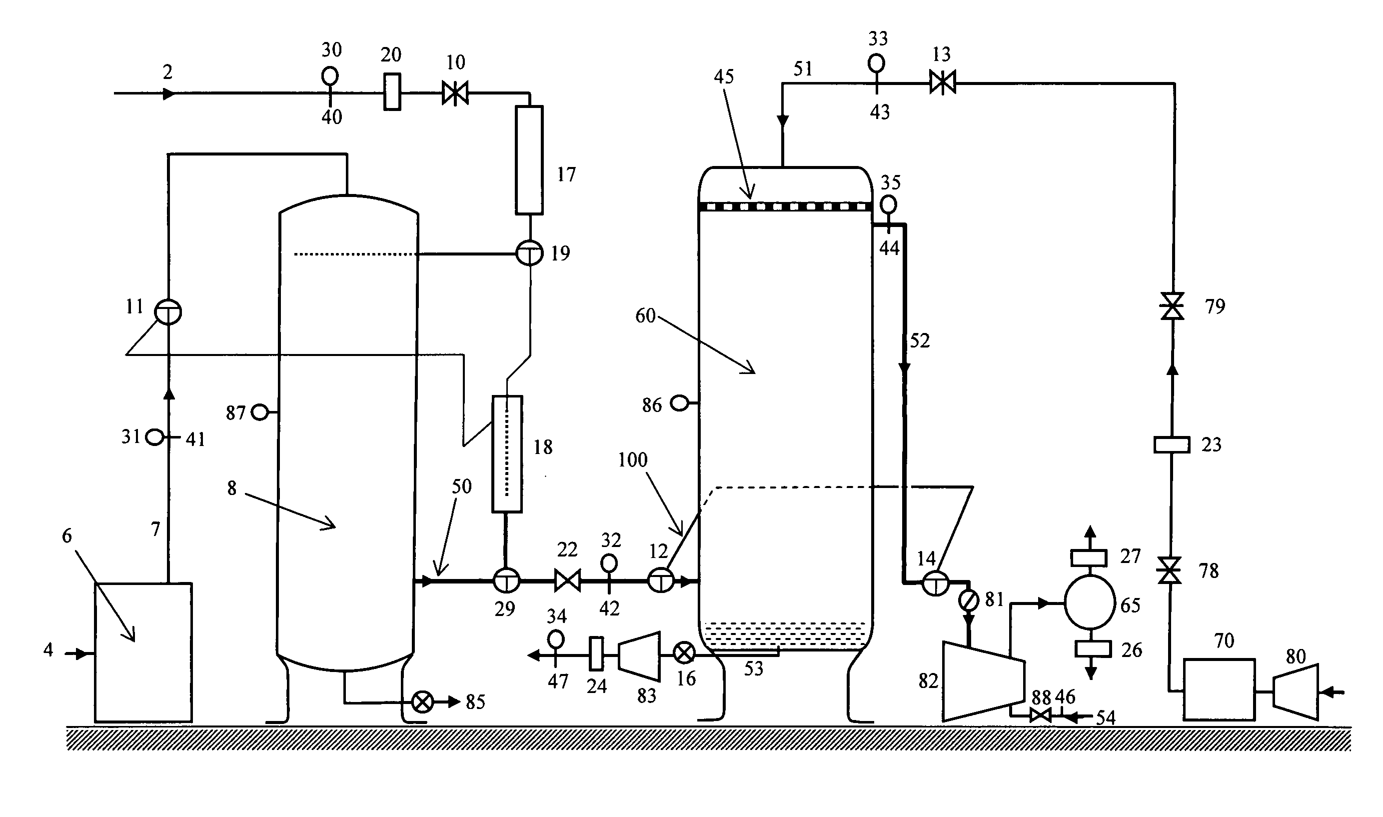
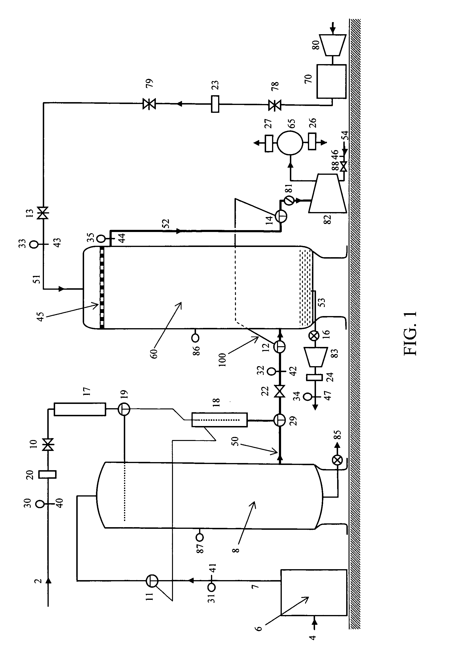
[0011]One aspect of the instant invention is the development of a condenser steam-air mixture exhaust simulator5 that duplicates steam-air mixture exhaust from a power plant condenser to the PCD or to the inlet of
vacuum pump or the suction of steam jet air ejector. One embodiment of the simulator comprises steam from a steam generator, air injection with
air heater, a mixer and a
vacuum pump as shown in FIG. 1 without an
expansion tank. An alternative embodiment of the condenser steam-air mixture exhaust simulator comprises steam from a steam generator, air injection with
air heater, an
expansion tank and a
vacuum pump as shown in FIG. 1 also. The
expansion tank is for mixing and expansion of
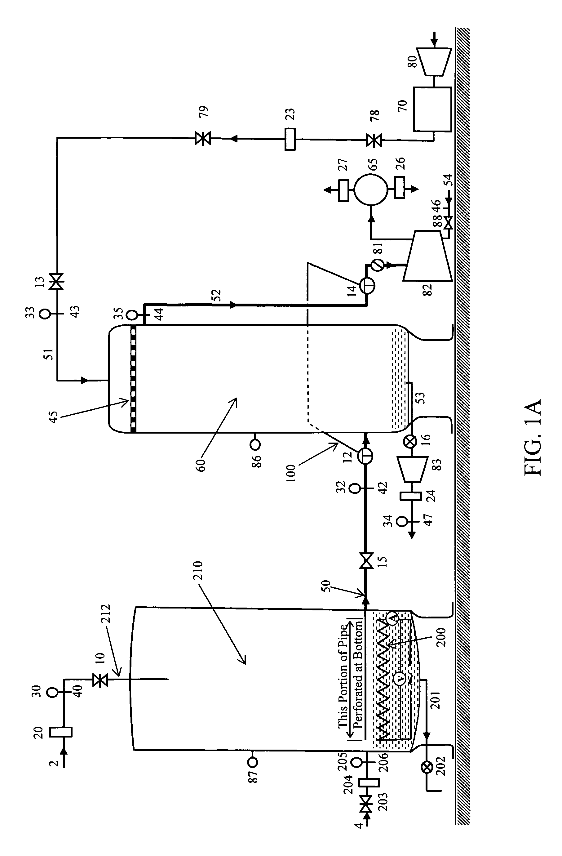
high pressure of steam and air entering the tank to lower pressure. Another alternative embodiment of the condenser steam-air mixture exhaust simulator having a vacuum pump, a heater, and appropriate water addition and air injection is shown in FIG. 1A. Any of these three embodiments can readily be incorporated into a prototype
test facility for Novel PCS Technology. With the condenser steam-air mixture exhaust simulator5, it is possible to study condensation
mass and
heat transfer data and to learn
operating procedures for this Novel PCS Technology for an optimum reduction of air inventory in a condenser. With these data and procedures, the design and performance of PCD can be greatly improved. In addition, the overall
heat transfer coefficients of the PCD can be obtained using this
test facility, which allows proper design of a
full scale demonstration of the novel PCS technology in a power plant.
[0012]Another aspect of the instant invention addresses an improved interface of the PCS with the air off-take
pipe of a power plant condenser. In U.S. Pat. No. 6,128,901, the PCS is simply connected to the air off-take
pipe of a power plant condenser. However, such a configuration is undesirable should the PCS not be working or needs repair, as power plant operations would be shut down. This invention addresses these situations by introducing a bypass loop5 to the existing air off-take
pipe and locates the PCD either in the air off-take pipe or the bypass loop. Two three-way ball valves could be
cut into an existing air off-take pipe to accommodate the bypass loop. The bypass loop introduces the following advantages: 1) when the
pressure control system is not working, operations can revert to the original design (without the PCS) without a power plant shut down; 2) the
pressure control system can be repaired on-site without interfering with power plant operation; and 3) it provides great flexibility to install PCS system especially for in-service condensers with space limitations; The novel PCS technology can be implemented in an easy, safe and non-intrusive manner as part of an existing power plant configuration. This makes the technology highly attractive and helps ensure its commercial viability.
[0013]The third novel aspect of this invention is the spraying means used in the pressure control device (PCD) for condensing steam in a steam-air mixture. A conventional
spray nozzle provides droplets flowing downward in a conical pattern such that some of the droplets will hit the wall of the PCD rather than being concentrated in the interior. An innovative
orifice plate6 allows liquid droplets with controlled size to flow downward uniformly to increase contact surface area between liquid droplets and the steam-air mixture. This
orifice plate greatly improve the efficiency of condensing steam of the steam-air mixture in the PCD. It is to be noted that there are many ways to condense steam in steam-air mixture. For example, the steam of steam-air mixture could be condensed after bubbling through
chilled water in a vertical long container or appropriate pressure can be used to condense the steam of the steam-air mixture. Still another alternate to a mixing vessel or PCD in a
pressure control system, suggested by Mr. Phil Yakimow is an in-inline steam condensing section. The condensing section would be comprised of a spray section in which the condenser steam-air mixture exhaust is exposed to a cooling mist of pressurized condensate. The spray would mix intimately with the condenser steam-air mixture exhaust and result in the steam condensing and thus reducing the pressure of the spray section. This also effectively reduces the volume of steam going to the TSLRVP or SJAE. The
piping to supply the cooling mist spray could be either internal or external to the air removal pipe coming from the condenser.
[0014]The relatively poor performance of current power plant condensers is mainly attributable to their air removal systems being inefficient and unable to remove or reduce the size of air pockets in condenser tube bundles. The technology taught in this invention: 1) enhances fundamental understanding of condensation
mass and heat transfer in a PCD leading to a better design and improving efficiency of a PCS; 2) introduces a by-pass loop avoiding shut down power plant due to failure of Novel PCS Technology, facilitating its introduction and making it commercially viable; and 3) improving efficiency by using an orifice plate for more efficient condensation of steam in the steam-air mixture in the PCD. In summary the Novel PCS Technology represents the most efficient air removal system for
steam power plant condensers at this time and it facilitates further improvement in design and performance of the orifice plate and advancement in fundamental understanding of condensation mass and heat transfer at very low pressure regimes and highly air enriched of steam-air mixtures.

