Reusable fall restrain supports and fall arrestor

a technology of support and support, which is applied in the direction of building types, construction, building material handling, etc., can solve the problems of not being able to reuse the bracket for subsequent projects, becoming scrap metal, and a lot of expensive practi

Active Publication Date: 2010-09-28
PERIMETER PROTECTION PROD LLC +1
View PDF48 Cites 24 Cited by
  • Summary
  • Abstract
  • Description
  • Claims
  • Application Information

AI Technical Summary

Problems solved by technology

Thus the brackets cannot be re-used for subsequent projects and become scrap metal.
New posts must be used on each subsequent story construction, a rather costly practice.
It has been found that screwing the base to the floor is not practical when securing the base to a steel I-beam.
A single unit base and post also does not allow for an attachment point for future use of accessories.
Clamping devices do not allow construction to be completed (including “closing in” the floors and roof) without the removal of the device.
This is impractical for building construction because it requires a grating.
None of the prior art has been implemented in this industry despite a long-felt need for a more cost-effective safety system.

Method used


Image

  • Reusable fall restrain supports and fall arrestor
  • Reusable fall restrain supports and fall arrestor
  • Reusable fall restrain supports and fall arrestor

Examples


Embodiment Construction

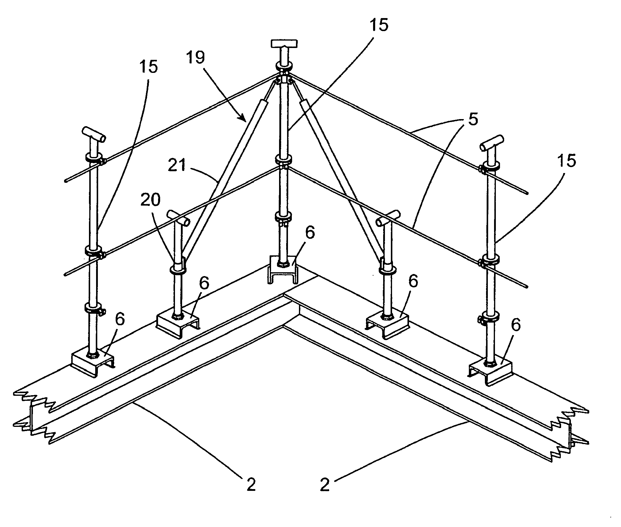
[0035]The reusable fall restraint support system comprises a disposable base and a reusable post. The base is welded to the I-beam. The post is then screwed into the base. FIG. 3A, FIG. 3B, and FIG. 3C are isometric drawings of two slightly different embodiments of the disposable base. With reference to the embodiment of FIG. 3A and 3C, the disposable base 6 comprises a section of a C-Channel 7 and two nuts 8 and 9 having female screw threads 10—the nuts being welded to opposite sides (top and bottom) of the “C” as shown. The two nuts act as female receptors into which the reusable post will be screwed. The disposable base is very inexpensive to manufacture and can be sold for a very low price. The embodiment of the base 6 depicted in FIG. 3A and FIG. 3C uses hexagonal nuts 8 and 9, while the embodiment of the base 6′ depicted in FIG. 3B uses square nuts 108 and 109. In a variation of the previously disclosed embodiments, a single nut with a female screw thread may be inserted into ...


PUM


Abstract

A system for providing re-usable safety support fences and fall restraints for the construction industry. The system comprises a plurality of disposable bases which are welded to I-beams or otherwise permanently attached to a floor or roof, and a plurality of removable support posts that screw into the disposable bases. The support posts form the posts of a safety fence through which steel cables are threaded to form a fence. Also, a fall arrestor, comprising an eye hook onto which a construction or maintenance worker on the perimeter of a building may attach, can be screwed into the permanently mounted disposable base. Additional embodiments for use with concrete construction instead of steel I-beams are disclosed.

Description

CROSS REFERENCE TO RELATED APPLICATIONS[0001]This Present application is the non-provisional counterpart of U.S. Provisional Application Ser. No. 60 / 908,963 (hereinafter the '963 application) filed on Mar. 9, 2007, into which the entire disclosure of U.S. Provisional Patent Application No. 60 / 825,670 was incorporated by reference, the entire disclosures both of which are incorporated herein by reference.BACKGROUND[0002]OSHA requires that construction workers working on high rise buildings are protected from falling by restraining devices. The Occupational Safety and Health Administration (OSHA) requires fall protection devices to be positioned around building perimeters, interior stairwells, and elevator shafts over six feet above grade. The most common method used by contractors is welding 4-ft 4-in ×4-in ×¼-in steel angles having holes drilled at the appropriate height to conform to OSHA requirements (see FIG. 1). The angle posts 3 are positioned vertically, as depicted, thereby f...

Claims


Application Information

Patent Timeline
Patent Type & Authority Patents(United States)
IPC IPC(8): E04H17/14
CPCE04G21/3223E04G21/3261E04G21/328Y10S256/06
Inventor MURPHY, THOMAS J.
Owner PERIMETER PROTECTION PROD LLC
Why Eureka
Try Eureka