Optimal spreader system, device and method for fluid cooled micro-scaled heat exchange

a spreader system and micro-scale technology, applied in the field of heat exchangers, can solve the problems of overheating of integrated circuits and miniaturization of electronic components, and achieve the effect of maximizing thermal performan

Active Publication Date: 2010-10-05
VERTIV CORP
View PDF388 Cites 43 Cited by
  • Summary
  • Abstract
  • Description
  • Claims
  • Application Information

AI Technical Summary

Benefits of technology

[0009]For fluid cooled micro-scaled heat exchangers to provide extremely high heat transfer area per unit volume, the geometric parameters of the exchangers must be considered carefully because these parameters have an influence on the convective heat transfer characteristics. Therefore, designs of systems using the present invention preferably optimize key parameters such as the pressure required to pump the cooling fluid, the flow rate, the hydraulic diameter of the channel, the temperature of the fluid and the channel wall, and the number of channels. The current invention provides optimized parameters, allowing the fluid cooled micro-scaled heat exchanger to serve as an efficient and economical means for removing high heat per unit volume.
[0010]The embodiments of the current invention provide specific types of spreaders used for fluid cooled micro-scaled heat exchange. Specific materials and ranges of dimensions that have been shown through simulations to yield major performance benefits are also disclosed within the current invention. Microchannels with high aspect ratios with depth / width ratios in the range of 10-50 are preferred for the micro-scaled heat exchanger, particularly for single-phase liquid flow. These aspect ratios allow large amounts of fluid to be pumped through the fluid cooled micro-scaled heat exchanger with optimized pressure drop, while simultaneously allowing the fluid to maintain a high thermal convection coefficient to the microchannel sidewalls in the microchanneled embodiment of the current invention.
[0012]The specific width for the micro-scaled and spreader regions are disclosed. In addition, the current invention discloses specific ranges of optimal dimensions of the micro-scaled and spreader regions that maximize thermal performance.

Problems solved by technology

The miniaturization of electronic components has created significant problems associated with the overheating of integrated circuits.

Method used


Image

  • Optimal spreader system, device and method for fluid cooled micro-scaled heat exchange
  • Optimal spreader system, device and method for fluid cooled micro-scaled heat exchange
  • Optimal spreader system, device and method for fluid cooled micro-scaled heat exchange

Examples


Embodiment Construction

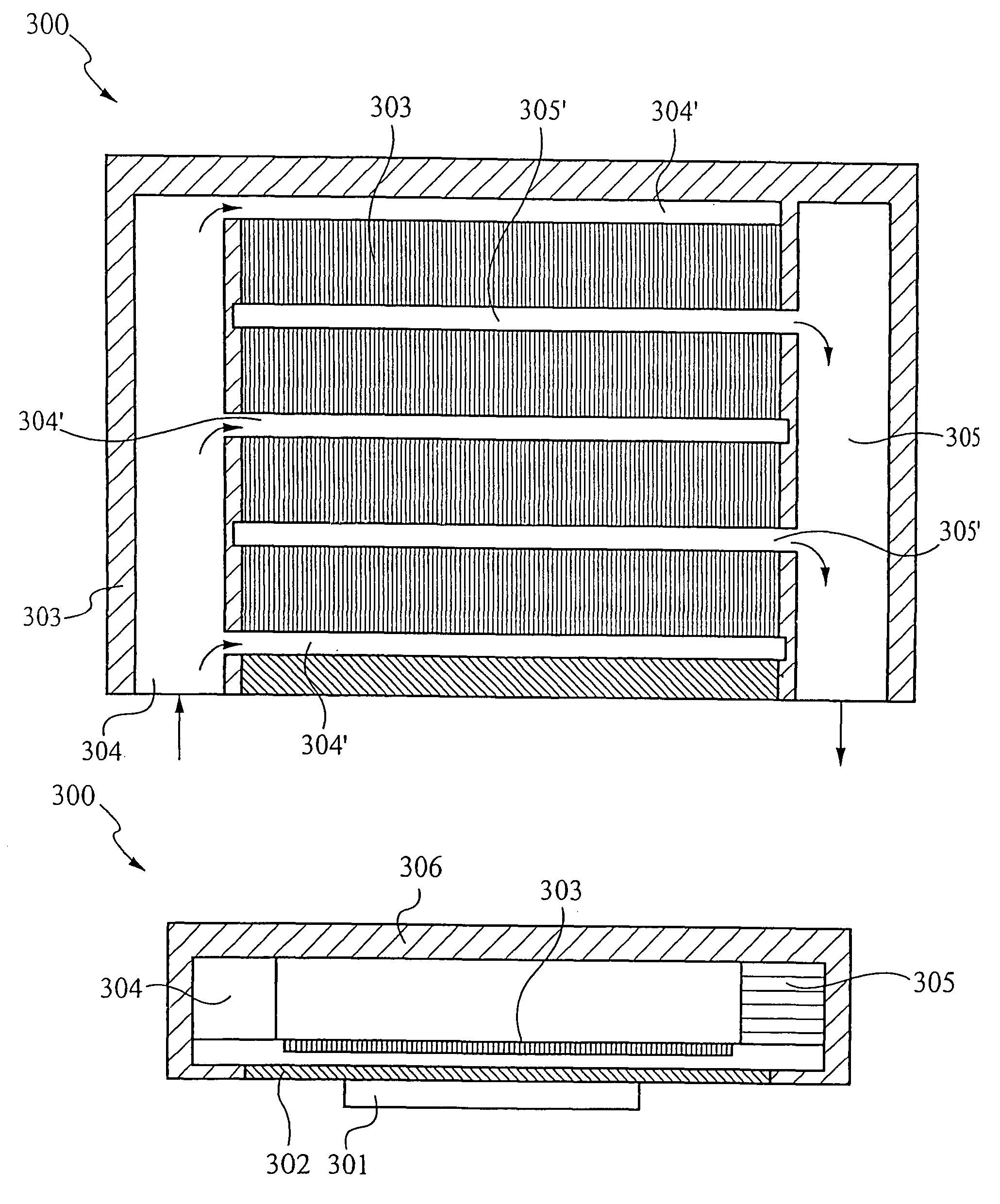
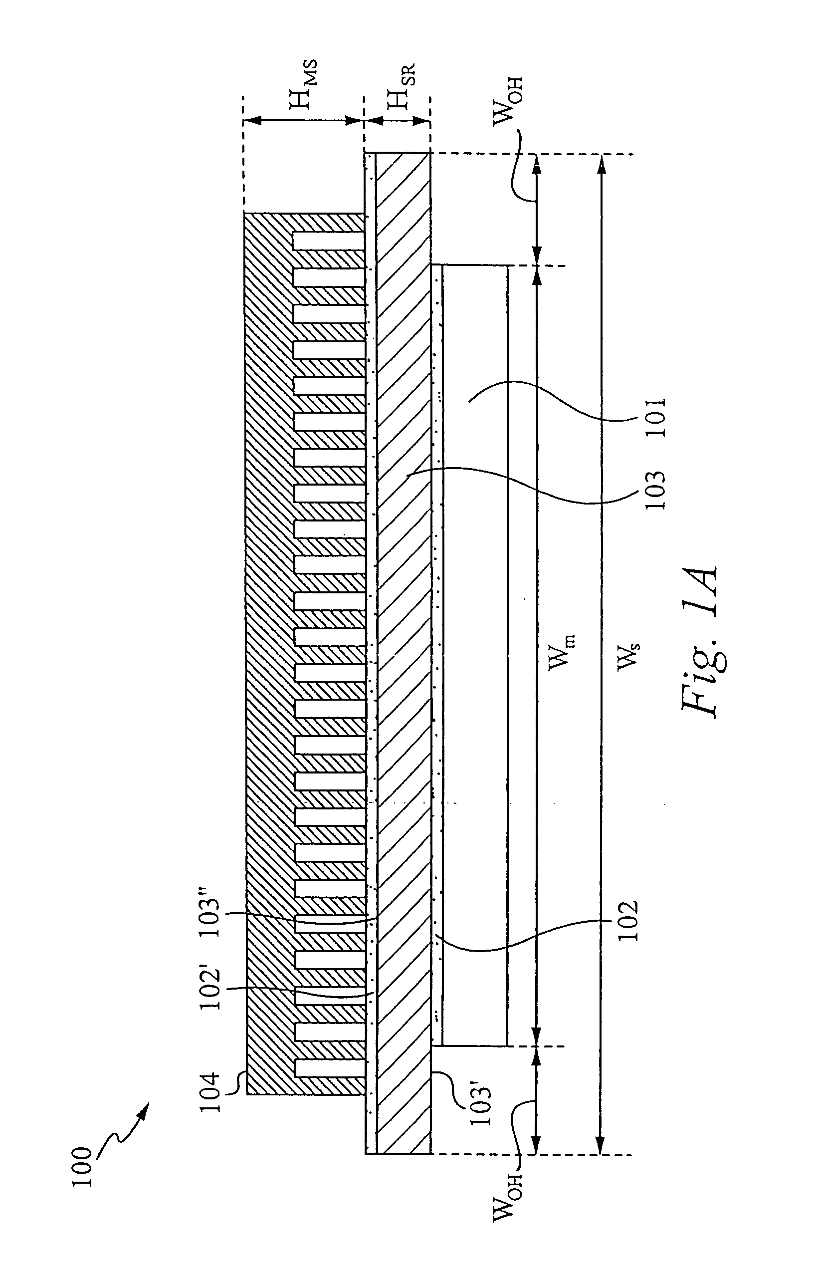
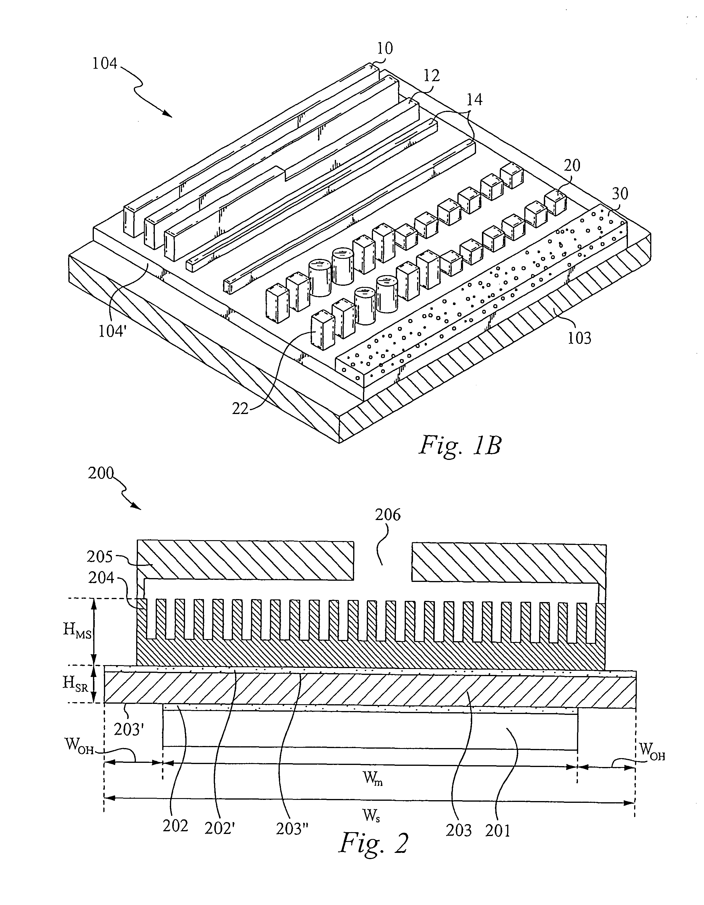
[0018]The geometric parameters of heat exchangers have a significant influence on their convective heat transfer characteristics. Therefore, designs according to the present invention preferably optimize key parameters of heat exchange such as: the pressure required to pump the cooling fluid; the flow rate; the hydraulic diameter of the channel; the temperature of the fluid and the channel wall; and the number of channels required. The current invention provides optimized parameters, allowing the fluid cooled micro-scaled optimized spreader to serve as an efficient and economical means for dissipating high heat per unit volume.

[0019]Embodiments of the current invention provide effective and efficient solutions for optimizing the absolute and relative dimensions of a fluid cooled micro-scaled heat exchanger, its spreader and micro-scaled regions, as well as the overhang of the micro-structure region with respect to a heat source (e.g. a microprocessor). The thickness and width of the...


PUM


Abstract

A device, method, and system for a fluid cooled micro-scaled heat exchanger is disclosed. The fluid cooled micro-scaled heat exchanger utilizes a micro-scaled region and a spreader region with a highly thermally conductive material and sized to yield high heat dissipation and transfer area per unit volume from a heat source. The micro-scaled region preferably comprises microchannels.

Description

RELATED APPLICATION[0001]This Patent Application claims priority under 35 U.S.C. 119 (e) of the co-pending U.S. Provisional Patent Application, Ser. No. 60 / 423,009, filed Nov. 1, 2002 and entitled “METHODS FOR FLEXIBLE FLUID DELIVERY AND HOTSPOT COOLING BY MICROCHANNEL HEAT SINKS” which is hereby incorporated by reference. This Patent Application also claims priority under 35 U.S.C. 119 (e) of the co-pending U.S. Provisional Patent Application, Ser. No. 60 / 442,383, filed Jan. 24, 2003 and entitled “OPTIMIZED PLATE FIN HEAT EXCHANGER FOR CPU COOLING” which is also hereby incorporated by reference. In addition, this Patent Application claims priority under 35 U.S.C. 119 (e) of the co-pending U.S. Provisional Patent Application, Ser. No. 60 / 455,729, filed Mar. 17, 2003 and entitled MICROCHANNEL HEAT EXCHANGER APPARATUS WITH POROUS CONFIGURATION AND METHOD OF MANUFACTURING THEREOF”, which is hereby incorporated by reference.FIELD OF THE INVENTION[0002]This invention relates to the field...

Claims


Application Information

Patent Timeline
Patent Type & Authority Patents(United States)
IPC IPC(8): F28F7/00F04B17/00F04B19/00F28D15/02F28F3/02F28F3/12H01L23/473H05K7/20
CPCF04B17/00F04B19/006F28D15/0266F28F3/02F28F3/12H01L23/473H01L2924/0002F28F2210/10H01L2924/00
Inventor UPADHYA, GIRISHHERMS, RICHARDZHOU, PENGGOODSON, KENNETHHOM, JAMES
Owner VERTIV CORP
Why Eureka
Try Eureka