Ion implanter and method for adjusting ion beam

a technology of ion beam and ion beam, which is applied in the field of ion beam implantation, can solve the problems of difficult implementation of technology, high cost, and inability to achieve perfect cross-sectional and achieve the effect of effective and economical adjusting the shape of ion beam

Active Publication Date: 2010-10-05
ADVANCED ION BEAM TECHNOLOGY INC
View PDF2 Cites 5 Cited by
  • Summary
  • Abstract
  • Description
  • Claims
  • Application Information

AI Technical Summary

Benefits of technology

[0014]Accordingly, discovery has been made of the present invention, which is believed to meet such a need as described above by way of providing a novel ion implante

Problems solved by technology

Although the ion beam is analyzed by the AMU, the shape (cross-sectional shape) of the ion beam usually is not perfect as required.
However, implementation of the technology is difficult, and usually requires a complex mechanism and a high cost.
However, for practical implanta

Method used


Image

  • Ion implanter and method for adjusting ion beam
  • Ion implanter and method for adjusting ion beam
  • Ion implanter and method for adjusting ion beam

Examples


first embodiment

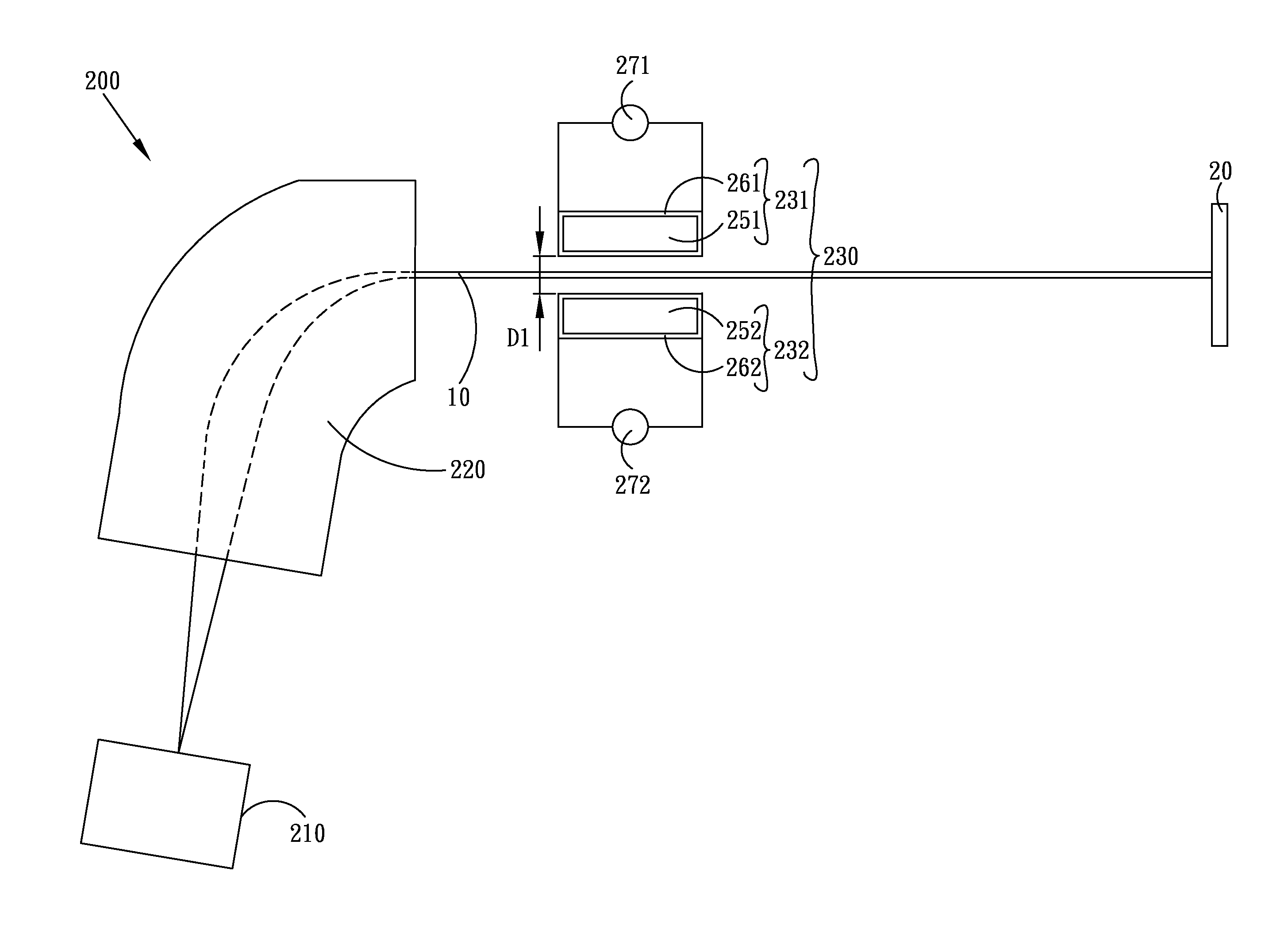
[0038]FIG. 2B shows the first set of bar magnets 230 shown in FIG. 2A. The first continuous loop of winding coils 261 includes a plurality of sections 2611-2613, wherein at least two different ones of the sections 2611-2613 have a different density of coils or coil density (turns / mm). That is, the coil density is the number of coils per unit length. Besides, the second continuous loop of winding coils 262 also includes a plurality of sections 2621-2623, wherein at least two different ones of the sections 2621-2623 have different coil density (turns / mm). Herein, the first continuous loop of winding coils 261 and the second continuous loop of winding coils 262 are non-uniformly distributed along the first support rod 251 and the second support rod 252 respectively.

[0039]In this embodiment, the distribution of the first continuous loop of winding coils 261 along the first support rod 251 is essentially similar to (e.g., about the same as) the distribution of the second continuous loop ...

second embodiment

[0041]FIG. 2C shows the first set of bar magnets 230 shown in FIG. 2A. The first continuous loop of winding coils 261 includes a plurality of sections 2611-2613, wherein at least two different ones of the sections 2611-2613 have different inductor coefficients, such as can be achieved from fabrication thereof from different materials. Moreover, the second continuous loop of winding coils 262 can also include a plurality of sections 2621-2623, wherein at least two different ones of the sections 2621-2623 have different inductor coefficients, such as by construction from different materials.

[0042]Again, the first set of bar magnets 230 can have only one continuous loop of winding coils being made of a different material with the other continuous loops of winding coils being made of the same material. Herein, different inductor coefficients will change power through the coils thereby slightly changing the diameters (e.g., via expansion) of the coils, such that a non-uniform magnetic fi...

third embodiment

[0043]FIG. 2D shows the first set of bar magnets 230 shown in FIG. 2A. The second support rod 252 is not straight and includes a plurality of sections 2521-2522, wherein at least two different ones of the sections 2521-2522 have different directions. Of course, the first support rod 251 also can be non-straight.

[0044]Clearly, when the distance between two support rods 251 / 252, or the distance between two continuous loops of winding coils 261 / 262, is varied along the direction of any support rod 251 / 252, the magnetic field distributed between the two support rods 252 / 252 will have multi-stages whereby the shape of the ion beam 10 will then be correspondingly adjusted.


PUM


Abstract

An ion implanter and method for adjusting the shape of an ion beam are disclosed. After an ion beam is outputted from an analyzer magnet unit, at least one set of bar magnets is used to adjust the shape of the ion beam when the ion beam passes through a space enclosed by the bar magnets. The set of bar magnets can apply a multi-stage magnetic field on the ion beam. Hence, different portions of the ion beam will have different deformations or alterations, because the multi-stage magnetic field will apply a non-uniform force to change the trajectory of ions. Moreover, each bar magnet of the set is powered by one and only one power source, such that the set of bar magnets essentially only can adjust the magnitude of the multi-stage magnetic field. Particular structures and techniques for achieving the multi-stage magnetic field are not limited.

Description

BACKGROUND OF THE INVENTION[0001]1. Field of the Invention[0002]The present invention generally relates to ion implantation, and more particularly, to an ion implanter and a method for adjusting a shape of an ion beam with a simple mechanism and relatively low cost.[0003]2. Description of the Prior Art[0004]Ion implantation processes are widely used in semiconductor manufacture, for example, to implant wafers with various ions having desired energy. Ion implantation processes typically require a uniform and consistent amount of ions to be implanted into a semiconductor wafer.[0005]A conventional ion implanter includes at least an ion source and an analyzer magnet unit (AMU). The ion source is used to generate an ion beam. The ion beam generated from the ion source is analyzed by the AMU before the required ions are implanted into a wafer. Although the ion beam is analyzed by the AMU, the shape (cross-sectional shape) of the ion beam usually is not perfect as required. For different ...

Claims


Application Information

Patent Timeline
IPC IPC(8): H01J37/317H01J49/20
CPCH01J37/147H01J37/3171H01J2237/083H01J2237/0835H01J2237/24542
Inventor JEN, KO-CHUANYANG, YORKWAN, ZHIMIN
Owner ADVANCED ION BEAM TECHNOLOGY INC
Why Eureka
Try Eureka