Buffer amplifier

a buffer amplifier and amplifier technology, applied in differential amplifiers, logic circuits, instruments, etc., can solve the problems of unsatisfactory increase of rising time and falling time of load capacitors, and negatively influence the transition time required for charging/discharging load capacitors

Inactive Publication Date: 2010-10-05
HIMAX TECH LTD
View PDF1 Cites 27 Cited by
  • Summary
  • Abstract
  • Description
  • Claims
  • Application Information

AI Technical Summary

Problems solved by technology

However, as the display resolution of the display panel is increased, the increased capacitance of each load capacitor substantially deteriorates the charge / discharge capability of the output buffer amplifier, thereby resulting in an undesirable increase of the rising time and the falling time of the load capacitor.
Thus, the degradation of the falling time may negatively influence the transition time required for charging / discharging of the load capacitor.

Method used


Image

  • Buffer amplifier
  • Buffer amplifier
  • Buffer amplifier

Examples


Embodiment Construction

[0013]The following description is of the best-contemplated mode of carrying out the invention. This description is made for the purpose of illustrating the general principles of the invention and should not be taken in a limiting sense. The scope of the invention is best determined by reference to the appended claims.

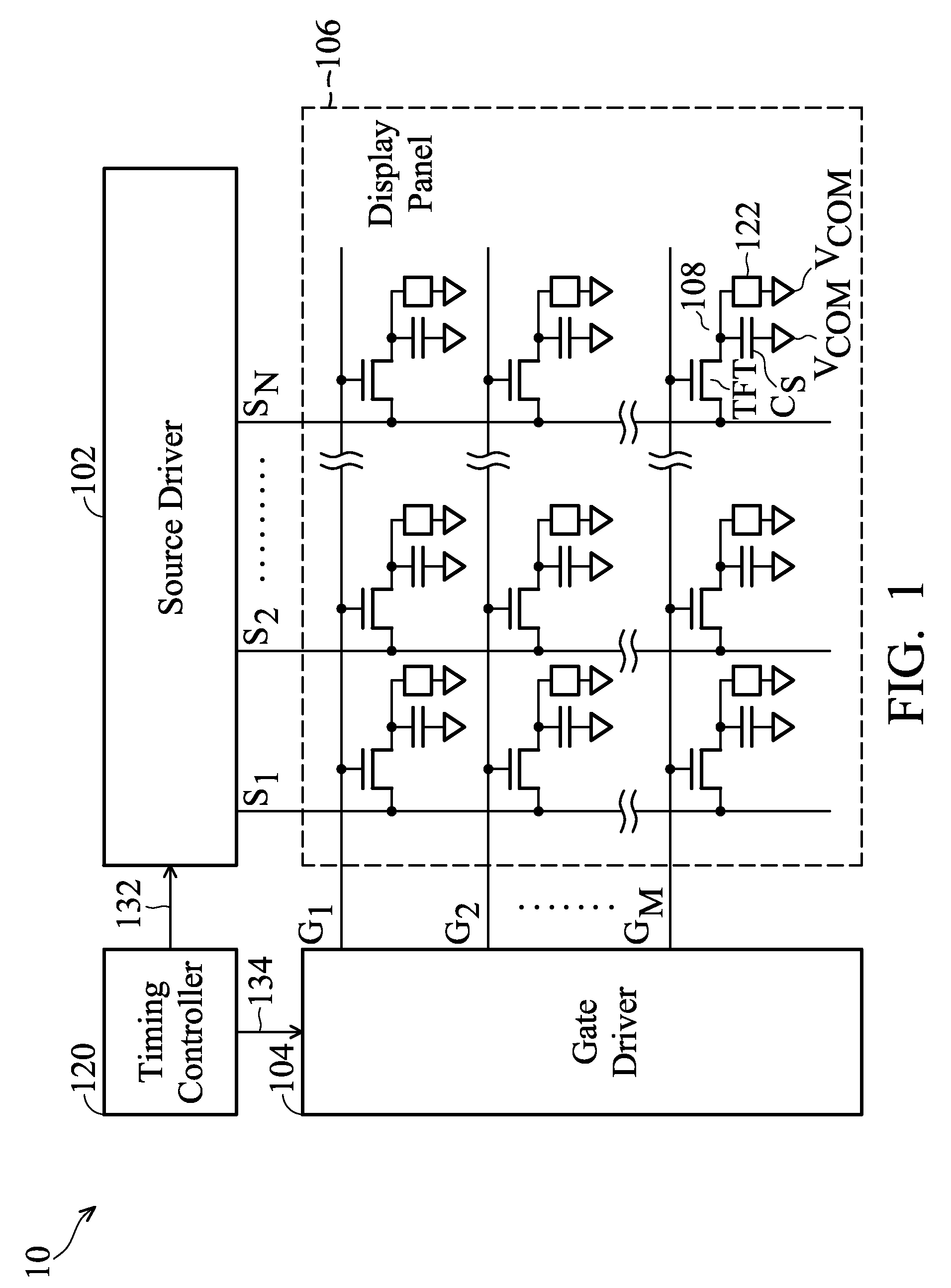
[0014]FIG. 1 is a schematic diagram illustrating a display system 10 according to an embodiment of the invention.

[0015]As shown in FIG. 1, the display system 10 comprises a source driver 102, a gate driver 104, a timing controller 120, and a display panel 106, such as a thin-film transistor liquid crystal display (TFT-LCD) panel. According to this embodiment, the display panel 106 comprises a plurality of display units, e.g., a display unit 108, arranged at intersections by columns of gate lines G1, G2 . . . GM, and rows of source lines S1, S2 . . . SN, to form a display matrix. During operation, the timing controller 120 provides timing signals 132 and 134 respectivel...


PUM


Abstract

A buffer amplifier includes an input stage circuit, an output stage circuit and a bias circuit, providing a buffered output signal at an output terminal according to an input signal applied to a first input terminal. The input stage circuit generates four control signals in response to the input signal when the logic level of the buffered output signal is opposite to that of the input signal. The output stage circuit includes four output transistors, wherein the first and second output transistor of a first type are provided for discharge in response to a first control signal and a second control signal, and the third and fourth output transistor of a second type are provided for charge in response to a third control signal and a fourth control signal. The bias circuit is used for determining the first, second, third and fourth control signal.

Description

BACKGROUND OF THE INVENTION[0001]1. Field of the Invention[0002]The invention relates to a buffer amplifier, and more particularly to a buffer amplifier for use in a source driver of a display panel.[0003]2. Description of the Related Art[0004]Nowadays, flat display panels, such as liquid crystal display (LCD) panels, are widely used in electronic devices due to their characteristics of lightweight, thinness and low power consumption. Generally, gate drivers and source drivers are arranged to drive the liquid crystal display panels through a plurality of gate lines and source lines. The gate drivers provide turn-on voltages to respective gate lines sequentially, and then the source drivers supply gray-level voltages, which are associated with image data to be displayed, to corresponding source lines. Further, a source driver generally comprises an output buffer amplifier to drive each panel load, e.g., a load capacitor of a display panel, to a desired state of charge / discharge accor...

Claims


Application Information

Patent Timeline
Patent Type & Authority Patents(United States)
IPC IPC(8): H03F3/45
CPCG09G3/3688H03K19/018528G09G2310/0291G09G2330/021
Inventor KUO, HUNG-CHANG
Owner HIMAX TECH LTD
Why Eureka
Try Eureka