Voltage reference circuit with low-power bandgap

a voltage reference circuit and low-power bandgap technology, applied in the field of radio frequency identification systems, can solve the problems of difficult harvesting of sufficient power from rf waves, and achieve the effect of reducing supply voltage and nano-ampere current levels

Active Publication Date: 2010-10-05
IMPINJ
View PDF9 Cites 25 Cited by
  • Summary
  • Abstract
  • Description
  • Claims
  • Application Information

AI Technical Summary

Benefits of technology

[0010]The invention offers the advantage of using a voltage reference circuit that allows working with a lower supply voltage and nano-ampere current levels. The circuit provides accurate reference voltage without the use of resistors or bipolar devices. In some embodiments, an output current value may be substantially higher than was available with prior art.

Problems solved by technology

Harvesting sufficient power from the RF wave can be difficult since the voltage of the RF signal is in the range of approximately 200 mV, and a typical supply voltage for circuits of the RFID tag is one volt.

Method used


Image

  • Voltage reference circuit with low-power bandgap
  • Voltage reference circuit with low-power bandgap
  • Voltage reference circuit with low-power bandgap

Examples


Embodiment Construction

proceeds with reference to the accompanying Drawings, in which:

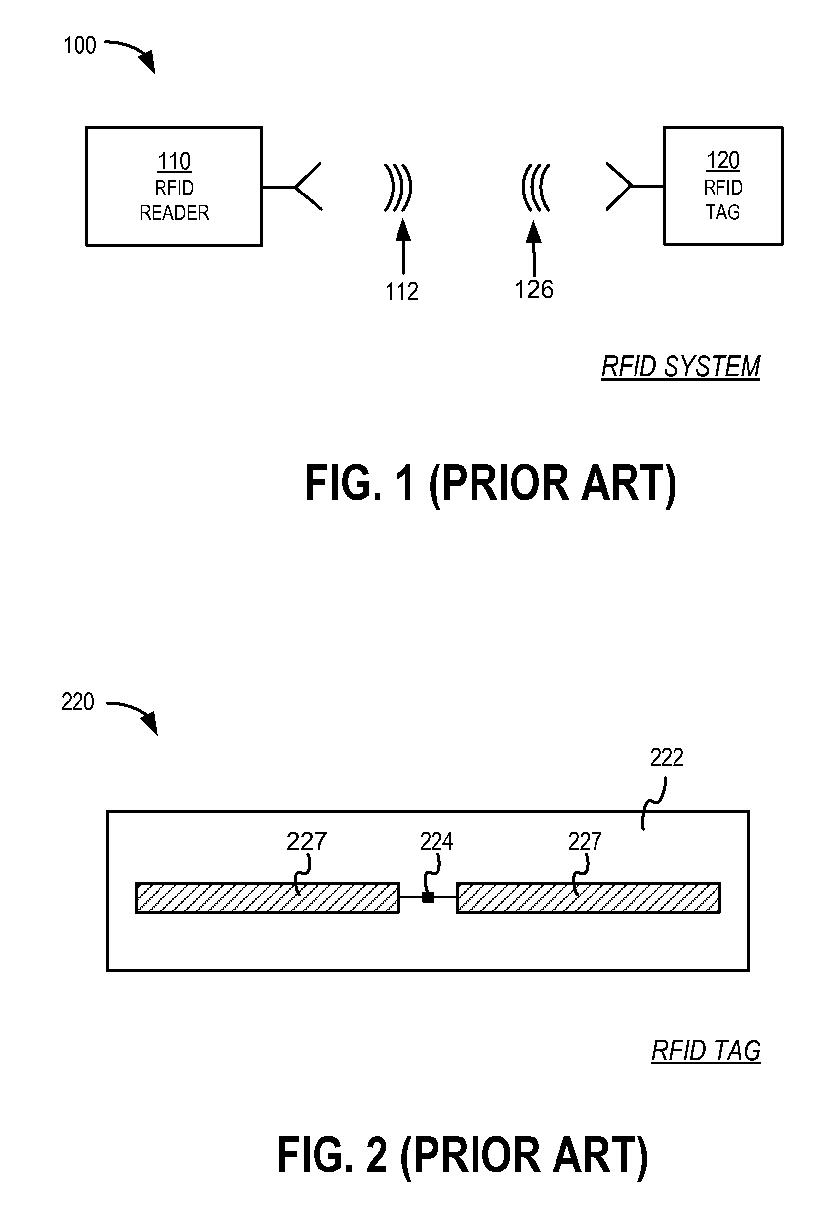
[0013]FIG. 1 is a block diagram of an RFID system.

[0014]FIG. 2 is a diagram showing components of a passive RFID tag.

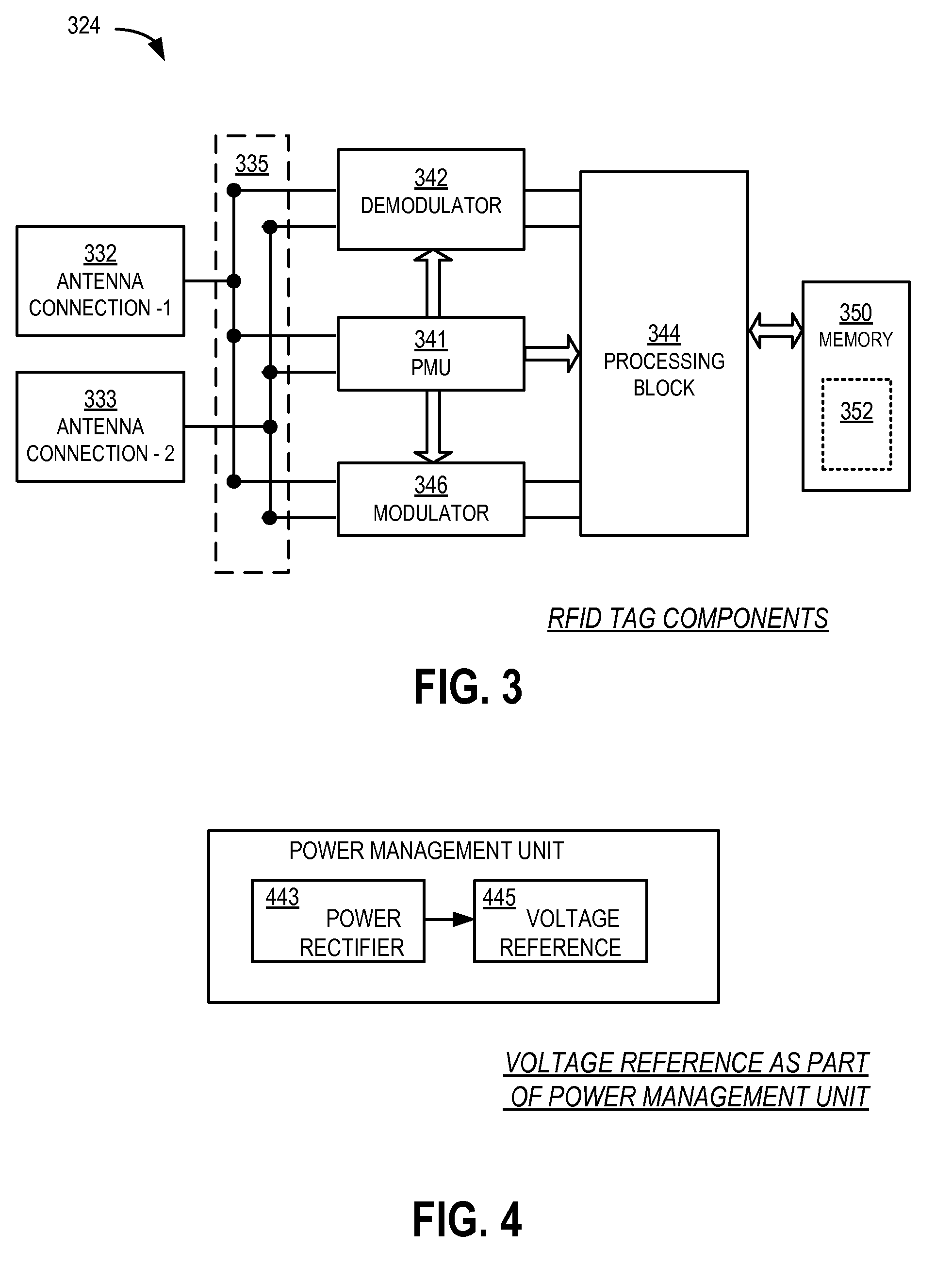
[0015]FIG. 3 is a block diagram of an implementation of an electrical circuit formed in an IC of the tag of FIG. 2.

[0016]FIG. 4 is a block diagram illustrating a voltage reference component of a Power Management Unit of the circuit of FIG. 3 according to embodiments.

[0017]FIG. 5 is a circuit diagram showing a bandgap reference circuit according to prior art.

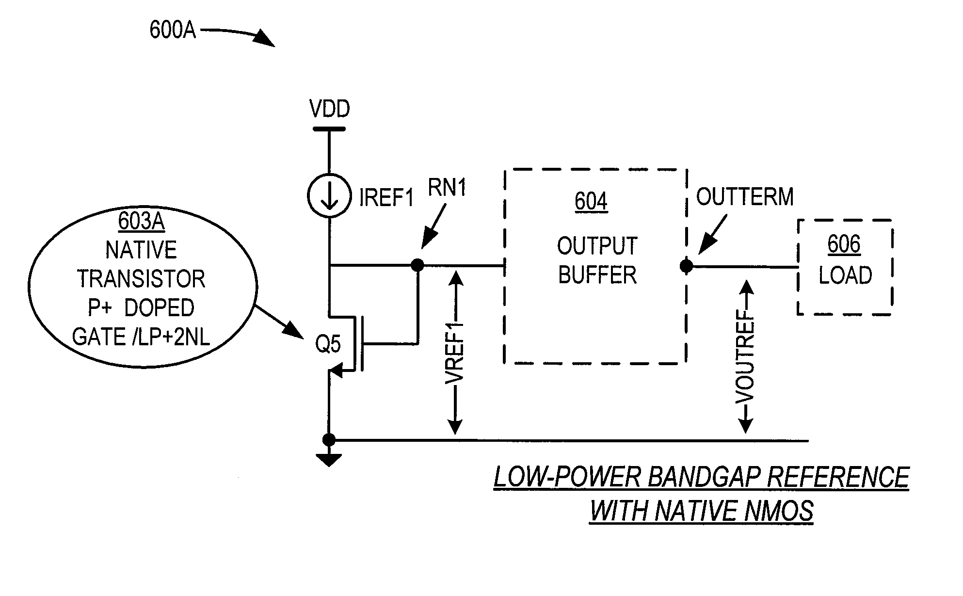
[0018]FIG. 6A is a circuit diagram showing a low-power bandgap reference circuit that includes a native NMOS transistor with reference to ground according to embodiments.

[0019]FIG. 6B is a circuit diagram showing a low-power bandgap reference circuit with native PMOS transistor with reference to ground according to an embodiment.

[0020]FIG. 6C is a circuit diagram showing a low-power bandgap reference circuit with native NMOS transistor with reference to...


PUM


Abstract

The present disclosure provides for a voltage reference circuit for Radio Frequency Identification (RFID) tag circuit. Such a circuit is formed in a substrate that is lightly doped with impurities of a first polarity. A first transistor having a first source connected to a ground, a first gate doped with impurities of the first polarity, and a first drain connected to the first gate at a reference node, a reference current source to provide a reference current to the reference node for generating a first reference voltage at the reference node, and an additional component for receiving the first reference voltage are disclosed.

Description

CROSS-REFERENCE TO RELATED APPLICATION[0001]This patent application claims priority from U.S. Provisional Patent Application Ser. No. 60 / 933,627 filed on Jun. 7, 2007, the disclosure of which is hereby incorporated by reference for all purposes.TECHNICAL FIELD[0002]The present disclosure addresses the field of Radio Frequency IDentification (RFID) systems, and more specifically RFID tags having one or more voltage reference circuits in their power management unit.BACKGROUND OF THE INVENTION[0003]Radio Frequency IDentification (RFID) systems typically include RFID tags and RFID readers. RFID readers are also known as RFID reader / writers or RFID interrogators. RFID systems can be used in many ways for locating and identifying objects to which the tags are attached. RFID systems are particularly useful in product-related and service-related industries for tracking objects being processed, inventoried, or handled. In such cases, an RFID tag is usually attached to an individual item, or ...

Claims


Application Information

Patent Timeline
Patent Type & Authority Patents(United States)
IPC IPC(8): G08B13/14
CPCG06K19/0701G06K19/0723
Inventor KUHN, JAY A.
Owner IMPINJ
Why Eureka
Try Eureka