Sensor

a sensor and sensor technology, applied in the field of sensors, can solve the problems of lowering the heating power demand of the sensor, and achieve the effects of improving the protection of the sensor element, reducing heat loss, and reliable protection

Inactive Publication Date: 2010-10-12
ROBERT BOSCH GMBH
View PDF25 Cites 11 Cited by
  • Summary
  • Abstract
  • Description
  • Claims
  • Application Information

AI Technical Summary

Benefits of technology

[0004]The sensor according to the exemplary embodiment and / or exemplary method of the present invention has the advantage that, by providing the central protecting tube within the double protecting tube, improved protection of the sensor element is achieved without affecting the dynamics of the gas sensor with regard to temperature fluctuations in the measuring gas. The additional central protecting tube, which is directly placed over the end section of the sensor element on the measuring gas side, offers reliable protection against thermal shock due to contact with water and reduces the heat losses on the heated sensor element occurring due to heat radiation and convection toward the measuring gas, so that the sensor reaches its operating temperature very quickly after being switched on and reliably maintains the operating temperature under all operating conditions.
[0005]Additionally, the reduced heat loss lowers the heating power demand of the sensor. Due to the measuring gas flow in the double protecting tube and in the space between the inner tube and the central protecting tube achieved by using the central protecting tube and due to the separation edges formed by the gas passage apertures in the central protecting tube, good turbulence of the measuring gas around the section of the sensor element on the measuring gas side is achieved which, together with the pulsation of the measuring gas, which typically occurs in the exhaust gas of internal combustion engines, causes a rapid exchange of the measuring gas in the interior of the central protecting tube.
[0006]Due to improved protection of the sensor element achieved by using the central protecting tube, the gas passage apertures in the double protecting tube may be designed to be larger so that they are not clogged by depositing particulates, e.g., soot. The particulates passing through the gas passage apertures in the double protecting tube are combusted on the hot tube casing of the central protecting tube since it is quickly heated to a temperature sufficient for the combustion process of these particulates due to the proximity to the heated sensor element and its rather thin wall. This improves the overall service life and dynamics of the sensor which are retained even under difficult operating conditions such as an individual cylinder regulation, for example.
[0007]The sensor according to the exemplary embodiment and / or exemplary method of the present invention may advantageously be used as a lambda sensor in internal combustion engines in which great temperature differences occur between idling and full load and the sensor must be installed in the exhaust pipe displaced back from the hot exhaust gas flow for reasons of overheating. Despite the associated longer heating time of the sensor housing after the cold start and the associated sometimes extended period during which the dew point is not exceeded on the housing mass during longer idling phases and at low outside temperatures, the sensor element is effectively protected.
[0009]According to an exemplary embodiment of the present invention, the protruding end of the inner tube of the double protecting tube is conically tapered like a cone frustum and sealed by a tube bottom, while the outer tube rests on the inner tube via a ring-shaped bottom part. The tube bottom of the inner tube has a front hole, and the ring-shaped bottom part or bottom ring has multiple gas passage apertures which are situated offset with respect to one another in the circumferential direction. Due to this constructive measure, a clearly improved measuring gas flow in the double protecting tube and between the inner tube of the double protecting tube and the central protecting tube is achieved, which causes optimal turbulence of the measuring gas within the central protecting tube.

Problems solved by technology

Additionally, the reduced heat loss lowers the heating power demand of the sensor.

Method used


Image

  • Sensor
  • Sensor

Examples


Embodiment Construction

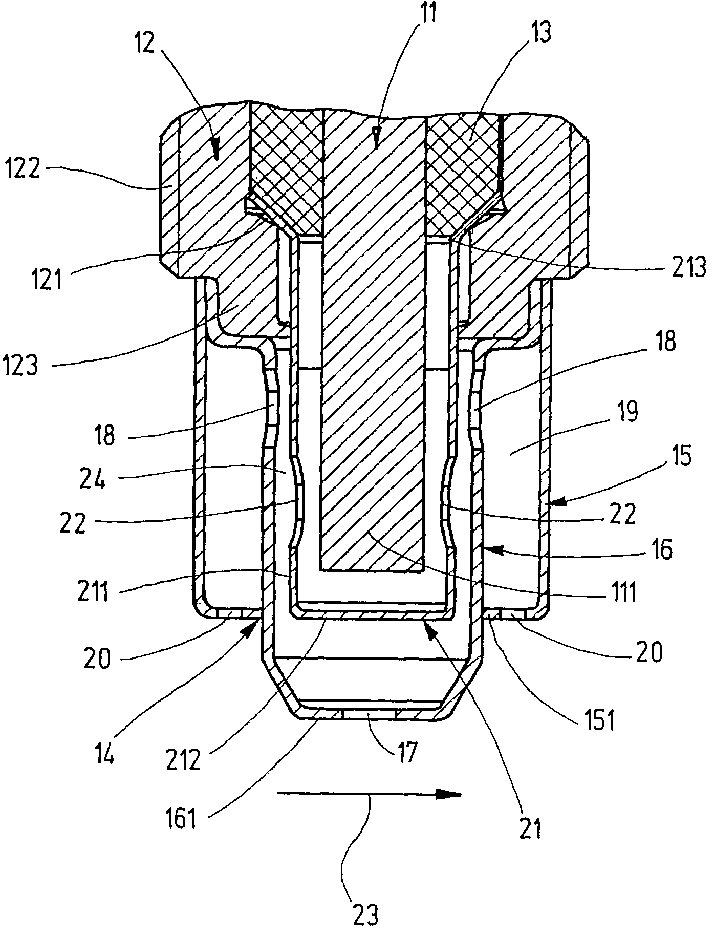
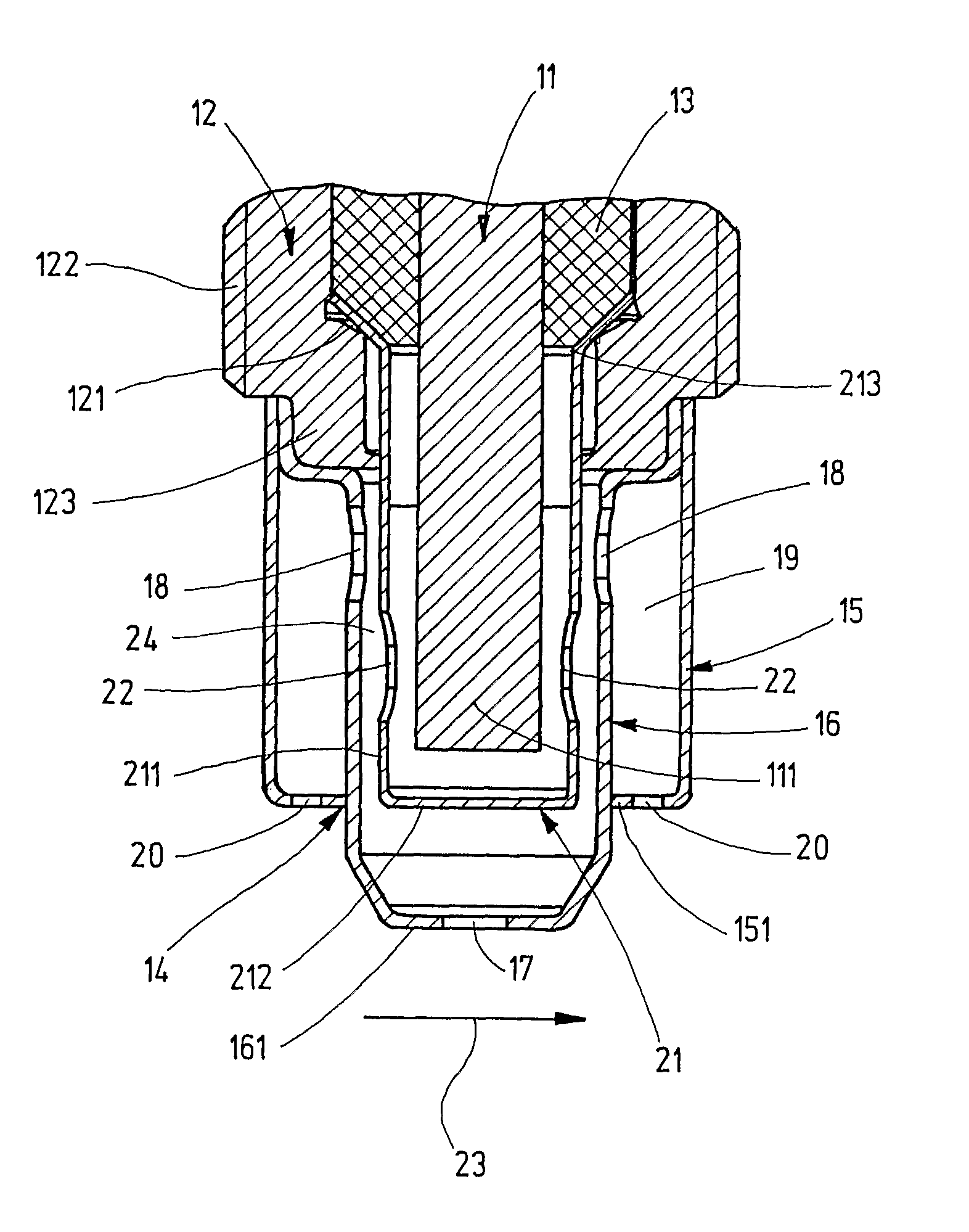
[0012]A three-way catalytic converter having a lambda regulation is used for reducing the exhaust emission of internal combustion engines. The lambda sensor illustrated in FIG. 1 in a schematic cross section is used for controlling the air / fuel mixture in order to set a mixture as close to the stoichiometric ratio as possible by measuring the oxygen content in the exhaust gas, so that the harmful emissions are minimized due to optimum combustion. This lambda sensor is described in the following as an exemplary embodiment for a general sensor used as a gas sensor with which a physical property of a measuring gas, e.g., the temperature of the measuring gas or the concentration of a gas component in the measuring gas, is measured.

[0013]The lambda sensor has a sensor element 11 made of a ceramic material including an end section 111 on the gas side exposed to the exhaust gas and an end section (not shown) on the connection side in which electrical contacting of sensor element 11 is esta...


PUM

PropertyMeasurementUnit
circumferenceaaaaaaaaaa
wall thicknessaaaaaaaaaa
physical characteristicaaaaaaaaaa

Abstract

A sensor, in particular a gas sensor for determining a physical characteristic of a measuring gas, in particular the temperature of the concentration of a gas component, in particular in the exhaust gas of an internal combustion engine, includes a sensor element which protrudes with a gas-side end section from a sensor housing and having a double protecting tube, which encloses the gas-side end section, and has an outer tube and an inner tube. For improved protection of the sensor element against thermal shock, a reduction in the heating power for the sensor element, and sufficiently high dynamics of the sensor, a cup-shaped central protecting tube is placed over the gas-side end section, the central protecting tube being provided with gas passage apertures in the tube casing, the gas passage apertures being positioned offset to the tube bottom with respect to the gas passage apertures present in the inner tube.

Description

FIELD OF THE INVENTION[0001]The present invention is directed to a sensor, in particular a gas sensor for determining a physical property of a measuring gas, in particular the temperature or the concentration of a gas component, in particular in the exhaust gas of an internal combustion engine.BACKGROUND INFORMATION[0002]For example, such sensors are used as lambda sensors for determining the oxygen concentration in the exhaust gas of an internal combustion engine. The sensor is provided with an integrated electrical heater in order to bring the gas-sensitive sensor element up to its operating temperature as quickly as possible, i.e., during the warm-up phase of the engine. The sensor element is made of ceramic materials. However, such ceramics are very sensitive to wide temperature fluctuations which result in cracks in the ceramic and bring about malfunctions and even total failure of the sensor. Extreme temperature fluctuations, also referred to as thermal shocks, occur on the su...

Claims


Application Information

Patent Timeline
Patent Type & Authority Patents(United States)
IPC IPC(8): G01N27/26G01N7/00G01K1/08G01N27/407
CPCG01N27/4077F01N3/2066F01N2610/02F01N2610/1453F01N2610/148Y02T10/12
Inventor WEYL, HELMUTHEINZELMANN, STEFANBUCHHOLZ, BASTIAN
Owner ROBERT BOSCH GMBH
Why Eureka
Try Eureka