Cart braking device

a technology of braking device and braking system, which is applied in the direction of braking system, friction lining, manufacturing tools, etc., can solve the problems of patient discomfort, damage to precision instruments, and inability to operate well, so as to reduce the damage of instruments and reduce the cost of expenditur

Inactive Publication Date: 2010-10-12
LIN CHING SUNG
View PDF13 Cites 23 Cited by
  • Summary
  • Abstract
  • Description
  • Claims
  • Application Information

AI Technical Summary

Benefits of technology

[0013]The cart braking device according to the present invention uses the curved surfaces of the braking pads to press against the shoulders of the wheel, which stops the rotation of the wheel and brakes the cart. After repeated use, the braking pads do not cause uneven wear on the circumferential center line of the tread surface, which is in contact with the floor, so the cart braking device according to the present invention effectively solves the problem of cart bumping on the floor. The cart having the cart braking device is suitable to transport precision instruments and very ill patients, which reduces instrument damages and provides comfortable ride for the patients during the transportation.
[0014]The curved surfaces of the braking pads can still effectively press against the shoulders of the wheel without loss of braking, even after the tread surface of the wheel around the circumferential center line shows signs of wear. Thus, it does not need to frequently replace the wheels and the cart braking device lowers the expenditure cost.
[0015]The orientation gear is push down to be engaged with the fixation gear of the braking member, when braking the cart. Thus, the orientation of the wheel is locked and the cart moves in a fixed direction. Moreover, the cart braking device according to the present invention can fix the orientation of the wheel at any angle.

Problems solved by technology

(1) The braking pad 103 is pressed against the tread surface of the wheel 107. After a period of time, the tread surface worn out. The braking pad 103 can no longer fully contact with the tread surface of the wheel 107, so the braking is not functioning well. Then, it needs to replaces the wheel 107.
(2) When the cart moves, the tread surface is contacted with the floor at a circumferential center line of the wheel 107. The braking pad 103 is directly pressed on the circumferential center line of the wheel 107. Repeated use of the cart braking device wears the wheel 107 and causes uneven wear on the tread surface at the circumferential center line of the wheel 107. The uneven tread surface results in cart bumping on the floor and collision of objects in the cart, when the cart moves. The disadvantage is serious, especially when the cart is used to transport very ill patient or precision instruments. It makes the patient uncomfortable and damages the precision instruments.
(3) When the projected arms 106 of the fixation piece 105 are engaged with the teeth 102 of orientation piece 101, end portions of the teeth 102 are in contact with sides of the projected arms 106. The end portions of the teeth 102 of the orientation piece 101 are rectangular and a pitch of the teeth 102 is large. Although elasticity of the orientation piece 101 can help the projected arms 106 to be engaged with the teeth 102, it has to rotate the orientation piece 101 at certain angles to engage the teeth 102 with the projected arms 106. Thus, the engagement of the teeth 102 and the projected arms 106 is intermittent but not continuous.

Method used


Image

  • Cart braking device
  • Cart braking device
  • Cart braking device

Examples


Embodiment Construction

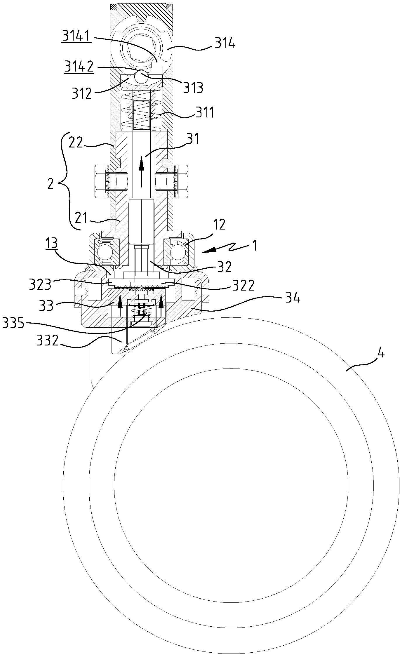
[0026]Referring to FIGS. 4-6, the cart braking device according to the presentation includes a swivel unit 1, a shaft unit 2 and a braking unit 3.

[0027]Referring to FIG. 4, the swivel unit 1 includes a wheel frame 11 pivotally connected with a wheel 4. The shaft unit 2 is mounted at a top of the swivel unit 1, and a bearing 12 is disposed between the swivel unit 1 and the shaft unit 2. Because of the bearing 12, the swivel unit 1 can rotate relative to shaft unit 2. Referring to FIGS. 5, 7, 8 and 9, the swivel unit 1 includes at least one orientation opening 13 disposed under the bearing 12. The orientation opening 13 is located in the direct front or rear of the swivel unit 1.

[0028]The shaft unit 2 includes a hollow shaft 21 and two shaft covers 22. The hollow shaft 21 includes two assembling holes 211 at a side wall thereof. A lower end of the hollow shaft 21 is fitted in the bearing 12. Each shaft cover 22 includes an assembling hole 221 and a through hole 223. A screw 222 passes...


PUM


Abstract

A cart braking device includes a swivel unit, a shaft unit and a braking unit which has a central shaft, an orientation member, a braking member and a base. The central shaft is coupled with the orientation member and has an elastic piece for moving the central shaft upward. A bottom of the orientation member has an orientation gear and a top of the braking member has a fixation gear corresponding to the orientation gear. The braking member is disposed in the base and includes two braking pads. An elastic member is disposed between the base and the braking member, and can move the braking member away from the base. When the braking pads are pressed against the wheel, the cart braking device stops the rotation of the wheel. When the orientation gear is engaged with the fixation gear, the cart braking device prevents the wheel from changing direction.

Description

BACKGROUND OF THE INVENTION[0001]1. Field of the Invention[0002]The present invention relates to a cart braking device, and in particular to a cart braking device has functions of wheel braking and directional locking.[0003]2. The Prior Arts[0004]A cart is used to carry merchandise, goods, luggage, etc. to provide laborsaving and convenient transportation. In order to prevent the cart from rolling when unattended by the user, a cart braking device is developed to eliminate the hazard caused by free-wheeling cart.[0005]A conventional cart braking device has various types, such as a handle type handbrake, a pedal type footbrake, etc. The conventional cart braking device usually uses a brake pad to directly press against a tread surface of a wheel, thereby stopping the movement thereof.[0006]Referring to FIGS. 1-3, a conventional cart braking device includes a central shaft 100, an orientation piece 101, a braking pad 103, a screw 104, and an fixation piece 105. The screw 104 connects ...

Claims


Application Information

Patent Timeline
Patent Type & Authority Patents(United States)
IPC IPC(8): B60B33/00
CPCB60B33/0021B60B33/0049B60B33/0057B60B33/0068B60B33/0073B60B33/0081B60B33/0092B60B33/021B60B33/025B60B33/026B60T1/04B62B5/04B60B33/0039Y10T16/195B62B5/0485
Inventor LIN, CHING-SUNG
Owner LIN CHING SUNG
Why Eureka
Try Eureka