Light receiver and Fresnel lens used therein

a light receiver and lens technology, applied in the field of light receivers, can solve the problems of large size, high cost, and unusable wired transmission, and achieve the effect of high light collection efficiency of light signals

Inactive Publication Date: 2010-10-12
PANASONIC CORP
View PDF8 Cites 11 Cited by
  • Summary
  • Abstract
  • Description
  • Claims
  • Application Information

AI Technical Summary

Benefits of technology

[0015]The present invention provides a light receiver having a low loss of a Fresnel lens, leading to a high light collection efficiency, and also provides a Fresnel lens used in the light receiver.
[0017]This structure provides a light receiver which collects light signals from a large acceptance angle on the light receiving element, thereby achieving a high light collection efficiency of light signals incident within a certain acceptance angle.
[0019]This structure provides a Fresnel lens suitable for use in a light receiver which collects light signals from a large acceptance angle on the light receiving element, thereby achieving a high light collection efficiency of light signals incident within a certain acceptance angle.

Problems solved by technology

However, wired transmission is not user-friendly partly because it requires cable connection.
However, the conventional high-speed optical wireless transmission device uses an optical-axis adjusting mechanism to ensure received optical power, thereby having a lot of requirements such as the large size.
Thus, unfortunately, the light receivers using these conventional optical-axis adjusting mechanisms are large in size and expensive.
The lens 800 has a problem of lens loss due to its prismatic shape.
As a result, the lens 800 has a larger lens loss.
Thus, the conventional light receiver 802 using the lens 800 has a problem that lens loss occurs in the lens 800 itself.

Method used


Image

  • Light receiver and Fresnel lens used therein
  • Light receiver and Fresnel lens used therein
  • Light receiver and Fresnel lens used therein

Examples


first embodiment

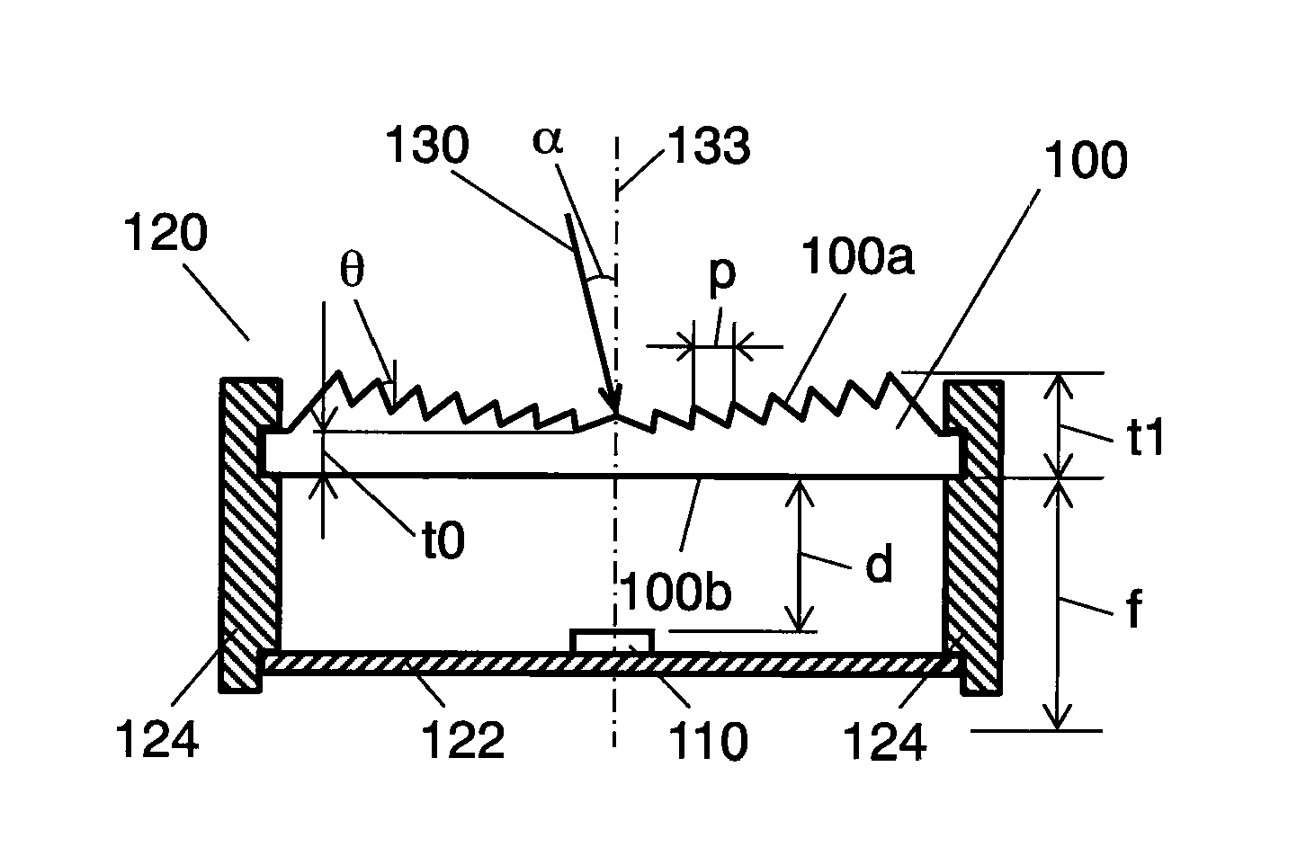
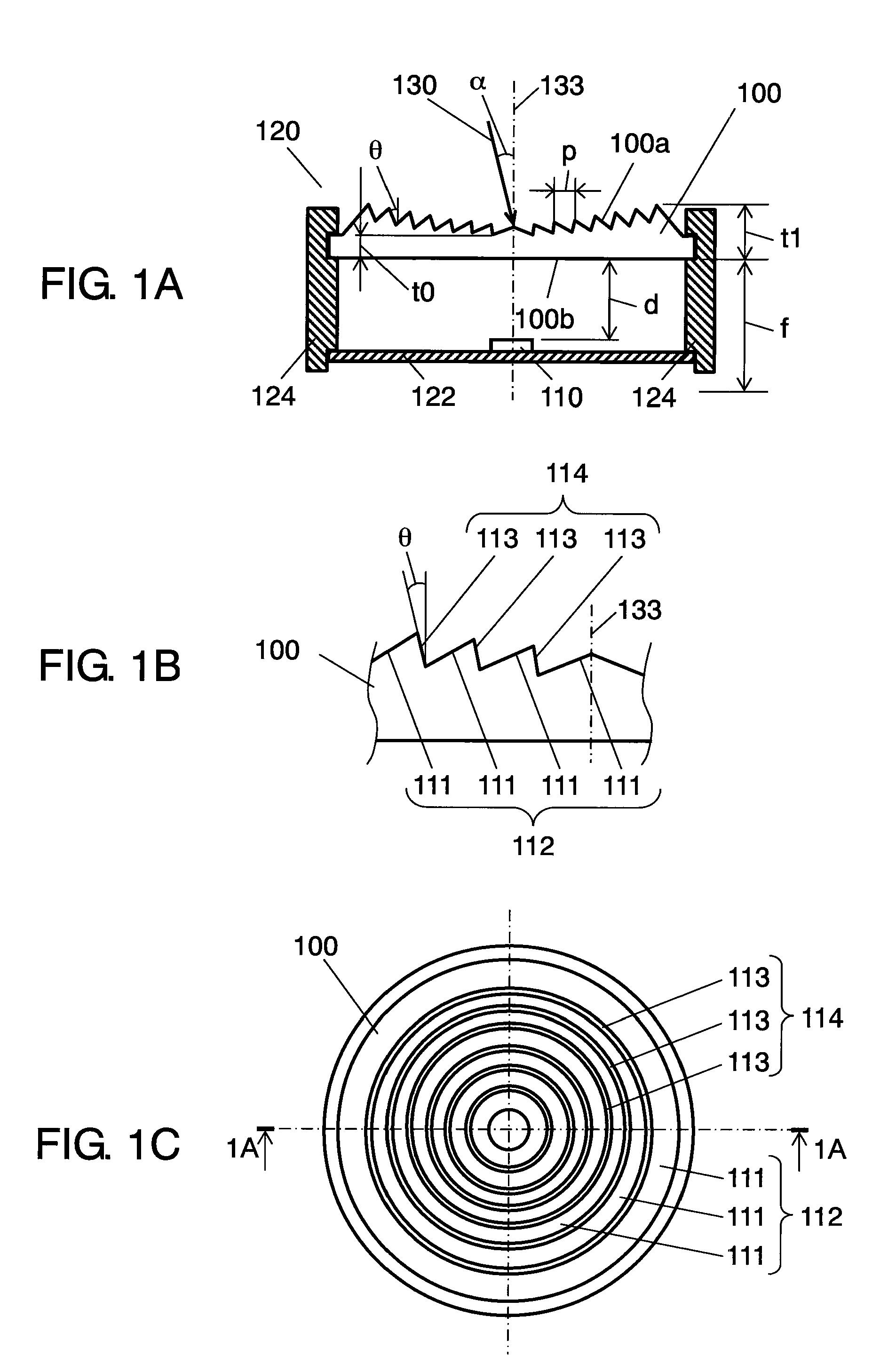
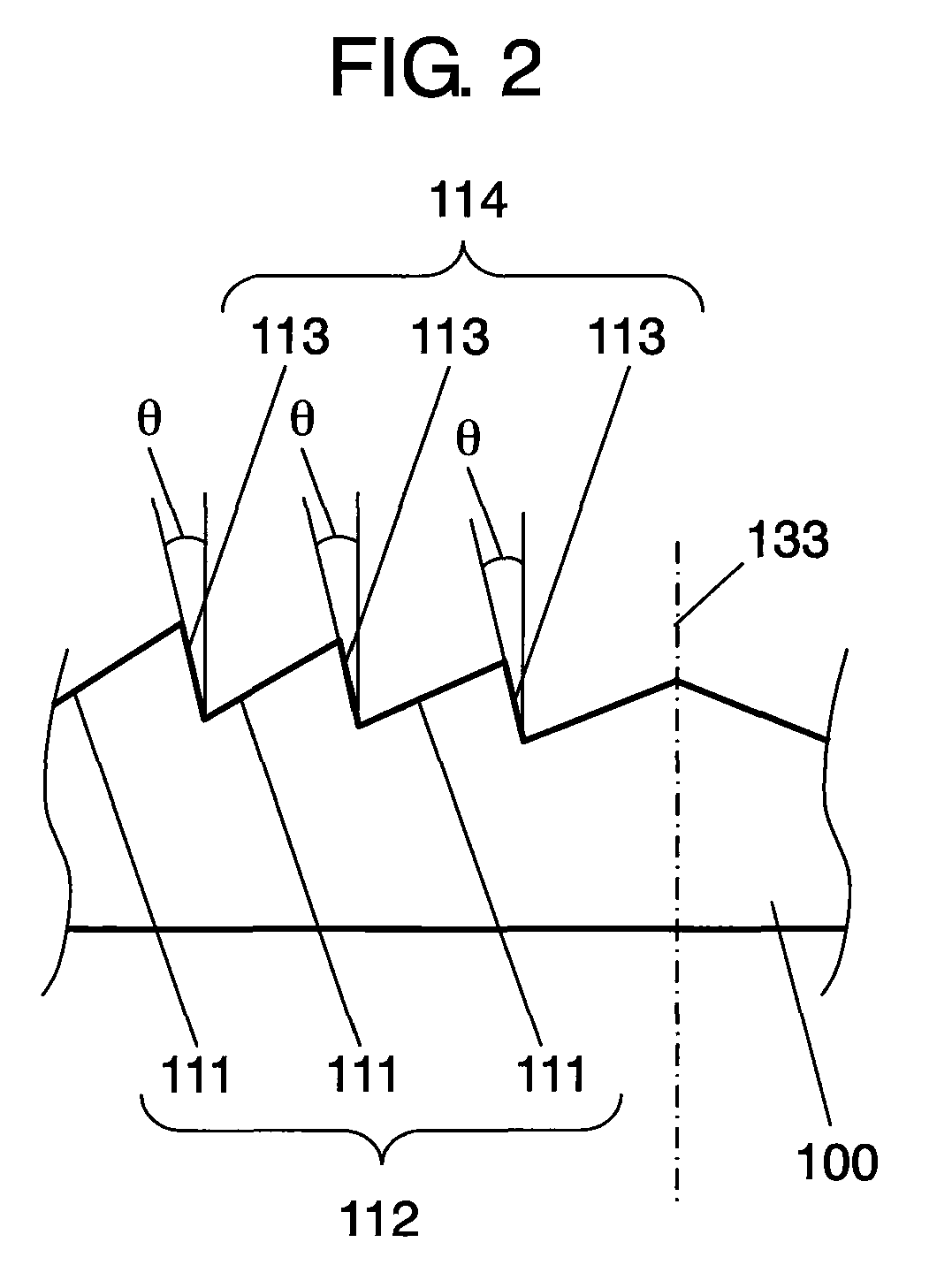
[0045]A light receiver 120 of a first embodiment according to the present invention will be described as follows with reference to the drawings. FIG. 1A is a sectional view of a light receiver 120. FIG. 1B is a partial sectional view of a Fresnel lens 100 (hereinafter, lens 100) used in the light receiver 120 of FIG. 1A. FIG. 1C is a plan view of the lens 100 of FIG. 1A when seen from the entrance surface 100a side. FIG. 2 is a sectional view showing the inclination angle θ of back cut surfaces 113 of the lens 100. FIG. 3A is a diagram showing a behavior of light signals 130 incident on the conventional Fresnel lens 800. FIGS. 3B and 3C are diagrams showing behaviors of light signals 130 incident on the lens 100. FIGS. 4A to 4D are diagrams showing behaviors of the light signals 130 incident on the lens 100.

[0046]As shown in FIG. 1A, the light receiver 120 comprises the lens 100, a light receiving element 110 (hereinafter, element 110), a substrate 122, and a holder 124. The lens 10...

second embodiment

[0073]A light receiver 120 of a second embodiment according to the present invention will be described as follows with reference to the accompanying drawings. The same components as those of the first embodiment are labeled with the same reference numerals and will not be described again in detail. The light receiver 120 of the second embodiment differs from the light receiver 120 of the first embodiment in that the Fresnel lens has additional features described below.

[0074]FIG. 6 is a partial sectional view of the Fresnel lens 200 (hereinafter, lens 200) used for the light receiver 120 of the second embodiment which is not shown in the drawings but has such a structure that the lens 100 of FIG. 1A is replaced by the lens 200. Similarly to the light receiver 120 of the first embodiment, the light receiver 120 of the second embodiment has the light receiving element 110, the substrate 122, and the holder 124.

[0075]As shown in FIG. 6, the lens 200 has a lens surface group 212 and a ba...

third embodiment

[0091]A light receiver 120 of a third embodiment according to the present invention will be described as follows with reference to the accompanying drawings. The same components as those of the first and second embodiments are labeled with the same reference numerals and will not be described again in detail. The light receiver 120 of the third embodiment differs from the light receivers 120 of the first and second embodiments in that the Fresnel lens has additional features described below. FIG. 8A is a sectional view of the light receiver 120 of the third embodiment. FIG. 8B is a sectional view of a Fresnel lens 300 (hereinafter, lens 300) of FIG. 8A.

[0092]As shown in FIG. 8A, the light receiver 120 comprises the lens 300, the light receiving element 110, the substrate 122, and the holder 124. The lens 300 has a first lens surface group 3121 and a second lens surface group 3122. The first lens surface group 3121 consists of a first lens surface 3111, a second lens surface 3112 and...


PUM


Abstract

A light receiver comprises a Fresnel lens for collecting light signals, and a light receiving element disposed closer to the Fresnel lens than the focal point of the Fresnel lens for receiving the light signals collected by the Fresnel lens. The Fresnel lens comprises a lens surface group having a plurality of lens surfaces, and a back cut surface group having a plurality of back cut surfaces connecting the lens surfaces. The back cut surfaces are inclined with respect to the center axis of the Fresnel lens. Thus, the light receiver has a high light collection efficiency of light signals incident within a certain acceptance angle.

Description

BACKGROUND OF THE INVENTION[0001]1. Field of the Invention[0002]The present invention relates to a light receiver which receives light signals transmitted through space, and to a Fresnel lens used in the light receiver.[0003]2. Background Art[0004]In recent years, mobile terminals typified by mobile telephones are becoming increasingly sophisticated, allowing the user to view large volumes of contents such as moving pictures on the terminals. Such large volumes of data are conventionally transferred to terminals by wired transmission. However, wired transmission is not user-friendly partly because it requires cable connection. To overcome the disadvantages of wired transmission, wireless transmission technologies such as wireless LAN have rapidly come into widespread use. Furthermore, the next generation high-speed wireless transmission technologies such as UWB (Ultra Wide Band) using electromagnetic waves have been actively developed. Optical wireless transmission systems also have...

Claims


Application Information

Patent Timeline
Patent Type & Authority Patents(United States)
IPC IPC(8): G02B3/08
CPCG02B3/08G02B3/10
Inventor YASUMOTO, HIDEOSASAI, HIROYUKI
Owner PANASONIC CORP
Why Eureka
Try Eureka