Electricity generating assembly

Inactive Publication Date: 2010-10-19
GREEN WILLIAM M
View PDF72 Cites 40 Cited by
  • Summary
  • Abstract
  • Description
  • Claims
  • Application Information

AI Technical Summary

Benefits of technology

[0009]The exemplary embodiments of the present invention relate to an electricity generating assembly that generates electricity from wind and / or water currents. The electrically operated shutter assembly prevents high winds, water currents and foreign objects, such as birds, from damaging the fan blades. Additionally, a sensor may be connected to a motor to close the shutters due to high winds or other environmental conditions that could damage the fan blades. Gearing is connected between the motor and the shutter assembly to move the plurality of shutters in unison.
[0012]According to another embodiment of the present invention, a pole-mounted wind generator assembly is provided in which the gearing is disposed between the fan blades and the generator. A further embodiment involves a stand-alone wind generator assembly in which the generator may be disposed within the fan blades and directly connected to a shaft to which the fan blades are connected. Alternatively, the generator for the stand-alone wind generator may be disposed outside of the fan blades, either connected to the fan blade shaft or offset from the fan blade rotation axis to increase the number of revolutions of the generator by a revolution of the fan blades. The stand-alone wind generator assemblies may be disposed in any desired location, such as a hilltop, roof top or open field.
[0013]Another advantage provided by the wind generator assembly according to the exemplary embodiments of the present invention is the ability to easily spread the production of electricity over a wide geographic area. Rather than relying on a single, central location for the supply of electricity, the present self-contained wind generator assemblies may be widely dispersed over a geographic area. An event that would shut down a single location supplying electricity, such as a tornado, hurricane or terrorist strike, would only minimally impact a widely dispersed wind generator assembly system according to exemplary embodiments of the present invention.

Problems solved by technology

Additionally, a sensor may be connected to a motor to close the shutters due to high winds or other environmental conditions that could damage the fan blades.

Method used


Image

  • Electricity generating assembly
  • Electricity generating assembly
  • Electricity generating assembly

Examples


Embodiment Construction

[0046]The present invention is described more fully with reference to the accompanying drawings, in which exemplary embodiments of the invention are shown. The present invention may, however, be embodied in many different forms and should not be construed as being limited to the exemplary embodiments set forth herein; rather, these exemplary embodiments are provided so that this disclosure is thorough and complete, and conveys the concept of the invention to those skilled in the art.

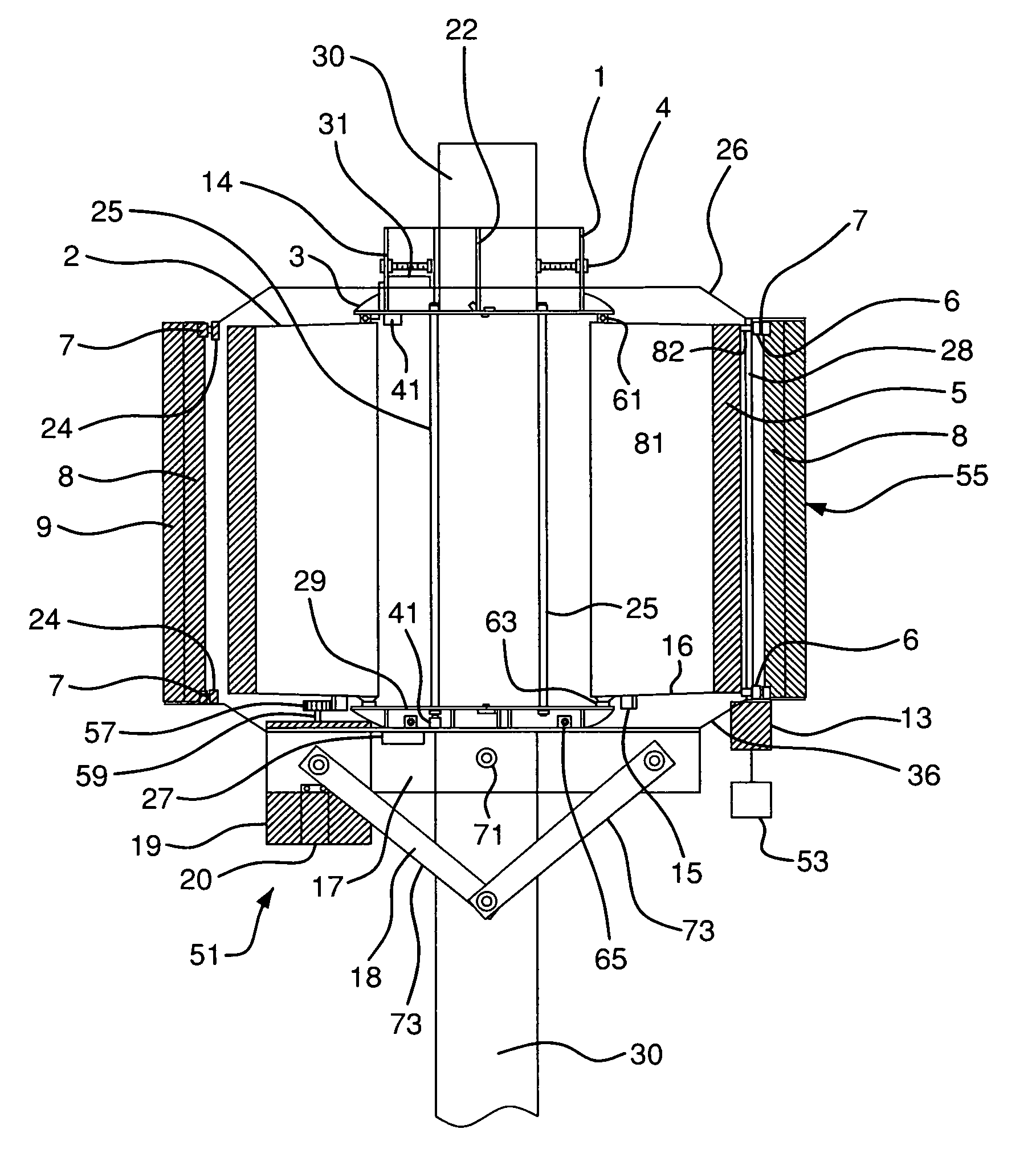
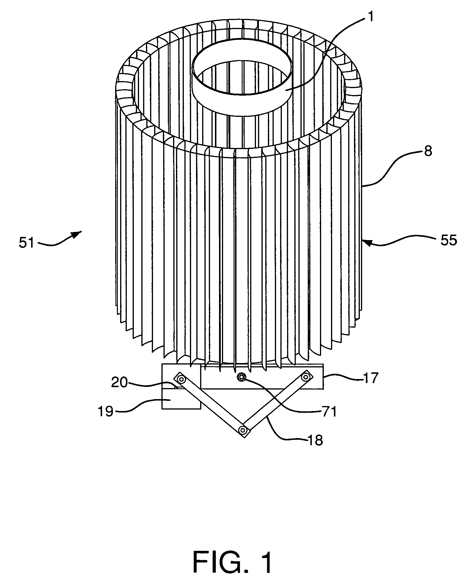
[0047]In a first exemplary embodiment of the present invention, the electricity generating assembly 55 is mounted to a pole 30 and the generator 19 is disposed externally of the plurality of fan blades 5, as shown in FIGS. 1 and 3. The generator 19 may include a gear box, transmission, and / or other suitable gear and power transmitting assemblies

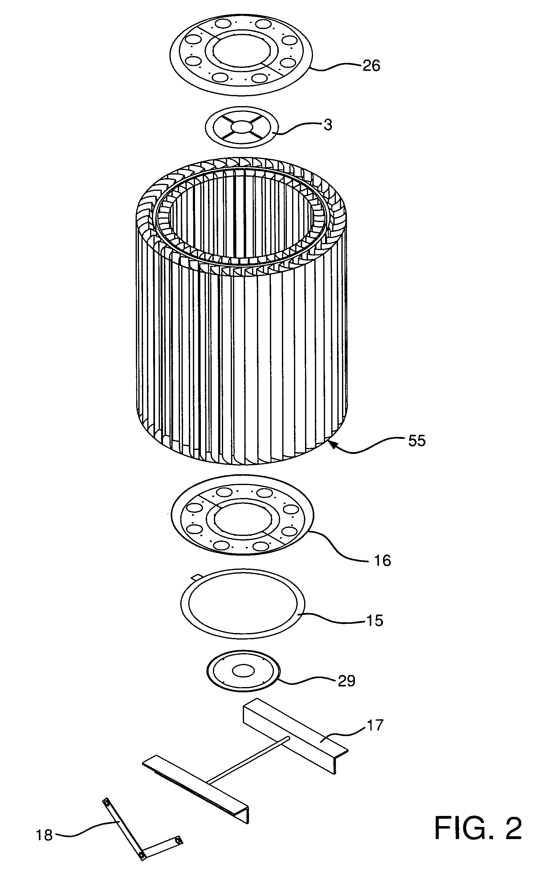
[0048]As shown in FIGS. 1-4, the electricity generating assembly 55 is mounted to a support, such as a telephone pole 30. A plurality of fan blades 5 are disposed...


PUM


Abstract

A electricity generating assembly includes a plurality of rotatable fan blades. A generator is connected to the plurality of fan blades to convert rotation of the fan blades into electricity. A plurality of shutters surround the plurality of fan blades. The plurality of shutters are movable between a first position in which said plurality of shutters are open to allow access to the plurality of fan blades and a second position in which the plurality of shutters are closed to prevent access to the plurality of fan blades. A motor is connected to the plurality of shutters to move the plurality of shutters between the first and second positions.

Description

CROSS REFERENCE TO RELATED APPLICATIONS[0001]This application claims the benefit under 35 U.S.C. §119(e) of provisional application Ser. Nos. 60 / 849,842, filed Oct. 6, 2006 and 60 / 915,591, filed May 2, 2007, the entire disclosures of both of which are hereby incorporated by reference.FIELD OF THE INVENTION[0002]The present invention relates to an electricity generating assembly that utilizes fluid currents or flow to produce electricity. More particularly, the present invention relates to a wind generator assembly having an electrically driven shutter assembly. Furthermore, the present invention relates to a electricity generating assembly that uses water to produce electricity. Still more particularly, the present invention relates to an electricity generating assembly that is remotely operable.BACKGROUND OF THE INVENTION[0003]Wind generators have long existed in which electricity is produced by rotation of a fan by wind. If the wind generators have no protection or shielding, such...

Claims


Application Information

Patent Timeline
Patent Type & Authority Patents(United States)
IPC IPC(8): F03D9/00H02P9/04
CPCF03D3/005F03D11/04H02K7/183F05B2240/215F05B2240/911Y02B10/30Y02B10/70Y02E10/728Y02E10/74F03D3/0409F03D9/007F03D9/008F03D9/11F03D9/25F03D9/34F03D13/20F03D13/25H02S10/12Y02E10/50Y02E10/727Y02E70/30
Inventor GREEN, WILLIAM M
Owner GREEN WILLIAM M
Why Eureka
Try Eureka