Peak factor reduction unit and baseband signal processing device

a signal processing and peak factor technology, applied in the field of peak factor reduction units and baseband signal processing devices, can solve the problems of significant instability in filter phase characteristics and difficult filter design, and achieve the effect of reducing the occurrence of phase distortion in an alias image eliminating analog filter, and not reducing peak factor

Inactive Publication Date: 2010-10-19
HITACHI LTD
View PDF7 Cites 5 Cited by
  • Summary
  • Abstract
  • Description
  • Claims
  • Application Information

AI Technical Summary

Benefits of technology

[0026]To ease the specifications of an analog filter, for example, interpolation is effective. The interpolation is often employed in the field of digital Hi-Fi audio. According to this method, O-insertion is made for each input signal, then the signal is over-sampled. After that, the waveform of the signal is smoothed by a linear phase type digital interpolation filter, then subjected to a high speed D / A conversion process. As a result, the alias image is separated far from the baseband. And now, the alias image eliminating analog filter can be selected freely from any of those that are slow in cut-off characteristics, simple in configuration, and less distorted in low orders. In spite of this, if a peak factor reduced signal is interpolated, the interpolation filter functions to generate a new problem that a once-deleted peak is reproduced.
[0049]According to an embodiment of the present invention, therefore, the peak factor reduction effect is not lost even upon execution of interpolation. So, occurrence of phase distortions in an alias image eliminating analog filter is reduced. In addition, in case where the polyphase structure is employed for the interpolation filter, peak factor reduction is realized at a low sample rate, thereby realizing a peak factor reduction unit employable for the interpolation functions built-in type D / A conversion IC as described above.

Problems solved by technology

The filter designing becomes difficult.
In addition, this case also includes a problem that the filter phase characteristics become unstable significantly around the cut-off.
In spite of this, if a peak factor reduced signal is interpolated, the interpolation filter functions to generate a new problem that a once-deleted peak is reproduced.

Method used


Image

  • Peak factor reduction unit and baseband signal processing device
  • Peak factor reduction unit and baseband signal processing device
  • Peak factor reduction unit and baseband signal processing device

Examples


first embodiment

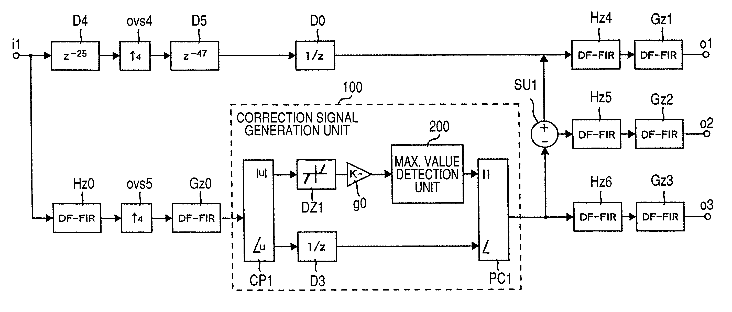
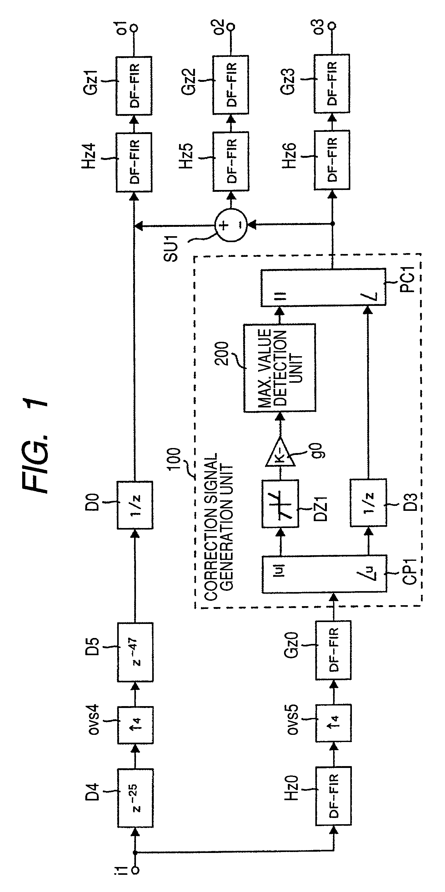
[0088]FIG. 1 shows a peak factor reduction unit in a first embodiment of the present invention. In FIG. 1, the same reference numerals will be used for the same components as those in a conventional peak factor reduction unit shown in FIGS. 16 and 20, avoiding redundant description. The configuration of the local maximum value detection unit 200 is the same as that shown in FIG. 16, so that its description will also be omitted here.

[0089]This first embodiment is characterized in that interpolation is completed before peak factor reduction is carried out in a subtraction unit SU1 so as to prevent peak reproduction to be caused by an interpolation filter Gz2. In the peak factor reduction unit in this first embodiment, an over-sampler ovs5 and an interpolation filter Gz0 are disposed between a baseband filter Hz0 and a correction signal generation unit 100 provided in the first path and an interpolation processing is carried out just after the band of an object input signal is limited ...

second embodiment

[0099]FIG. 4 shows a peak factor reduction unit in a second embodiment of the present invention.

[0100]The peak factor reduction unit in this second embodiment has a polyphase structure obtained by carrying out polyphase resolution for the peak factor unit in the first embodiment shown in FIG. 1. The signal response of the unit is equivalent to that in the first embodiment. FIGS. 5 and 7 show configurations of the peak factor reduction unit in intermediate stages, which realize the structures shown in FIGS. 1 through 4.

[0101]In the peak factor reduction unit shown in FIG. 1, the interpolation filter Gz0 is transformed so as to have a polyphase structure as shown in FIG. 24B and the polar-coordinates-to-complex CP1, the dead zone circuit DZ1, and the gain block g0 are disposed before the over-sampler ovs5. As a result, the peak factor reduction unit comes to be configured as shown in FIG. 5. Then, the interpolation filter Gz0 is subjected to polyphase resolution, thereby the filter Gz...

third embodiment

[0109]In the unit configuration shown in FIG. 7, the delay units D61 to D63 connected to the addition unit AD are subjected to noble identical transformation formally and disposed before the over-samplers ovs51 to ovs54. As a result, those delay units D61 to D63 come to have ¼, 2 / 4, and ¾ delays respectively. Actually, it is impossible to create a delay unit having such a fractional delay time. However, if those delay times may be just required to be approximate, a fractional delay FIR filter can replace those delay units.

[0110]The tap coefficient value of the fractional delay FIR filter can be obtained by using a useless detail time D and assume z=exp(jθ), then calculating a coefficient value “cn” so as to satisfy the following expression approximately for each of the three ways k=1, 2, and 3. In the following expression, the right side denotes a frequency response having a desired fractional delay and the left side denotes a frequency response of an approximate filter.

[0111]∑Cn⁢⁢e...


PUM


Abstract

A peak factor reduction unit that never allow peak factor reproduction even when interpolation is done in a succeeding stage. The unit detects a local maximum value of amplitude components from an input complex signal and supplies a complex signal that passes a band limiting baseband filter and an interpolation filter to a correction signal generation unit for generating a correction signal used for peak factor reduction and reduces a peak factor of the input complex signal with use of the correction signal generated from an interpolated complex signal.

Description

CLAIM OF PRIORITY[0001]The present application claims priority from Japanese application JP 2006-283545 filed on Oct. 18, 2006, the content of which is hereby incorporated by reference into this application.FIELD OF THE INVENTION[0002]The present invention relates to a peak factor reduction unit and a baseband signal processing device. More particularly, the present invention relates to a peak factor reduction unit and a baseband signal processing device preferred to a radio communication system for sending signals according to a normal distribution having a large peak factor, such as a base station of CDMA (Code-Division Multiple Access), OFDM (Orthogonal Frequency-Division Multiplexing), or the like.BACKGROUND OF THE INVENTION[0003]Radio communication techniques have been developed remarkably in recent years. Various modulation methods such as the third generation mobile communication system CDMA, the OFDM expected as the mainstream of the fourth generation communication systems, ...

Claims


Application Information

Patent Timeline
Patent Type & Authority Patents(United States)
IPC IPC(8): H04L25/03H04B1/69H04J1/00H04J11/00H04J13/00
CPCH04B1/707H04L27/2624H04B2201/70706
Inventor HORI, KAZUYUKIARAI, HIDEAKIMURAKAMI, SHOUHEI
Owner HITACHI LTD
Why Eureka
Try Eureka