System, method and apparatus for RF directed energy

a directed energy and energy technology, applied in the field of electromagnetic (em) energy, can solve the problem that the inertia electron cannot keep up with high frequency

Inactive Publication Date: 2010-10-26
LOCKHEED MARTIN CORP
View PDF5 Cites 56 Cited by
  • Summary
  • Abstract
  • Description
  • Claims
  • Application Information

AI Technical Summary

Problems solved by technology

Even low inertia electrons can fail to keep up with high frequencies depending on material used in constructing a detector.

Method used


Image

  • System, method and apparatus for RF directed energy
  • System, method and apparatus for RF directed energy
  • System, method and apparatus for RF directed energy

Examples


Embodiment Construction

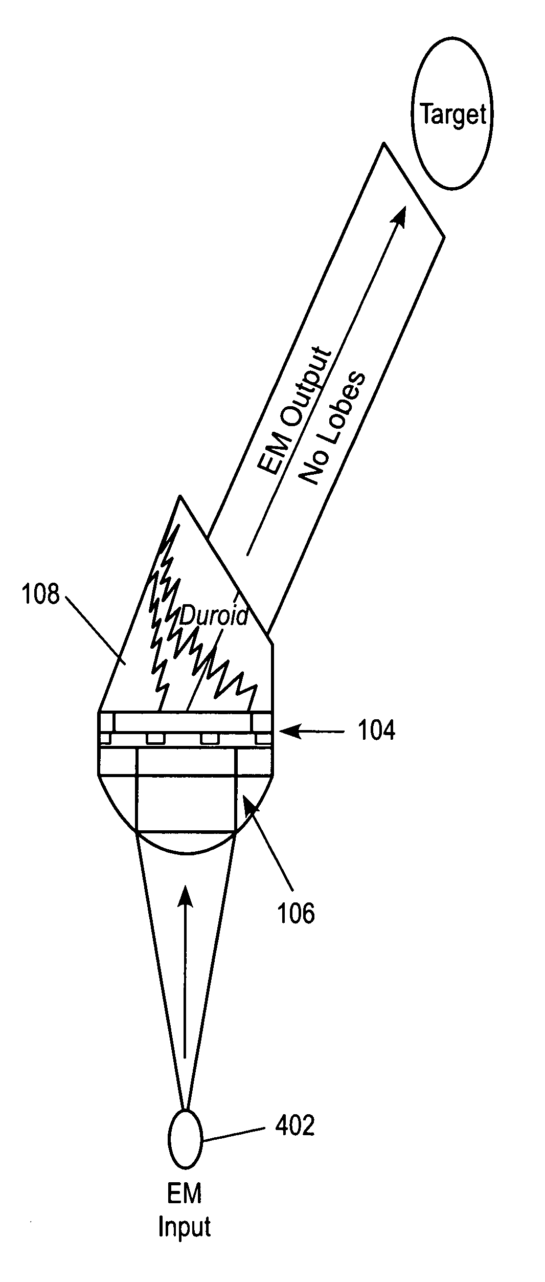
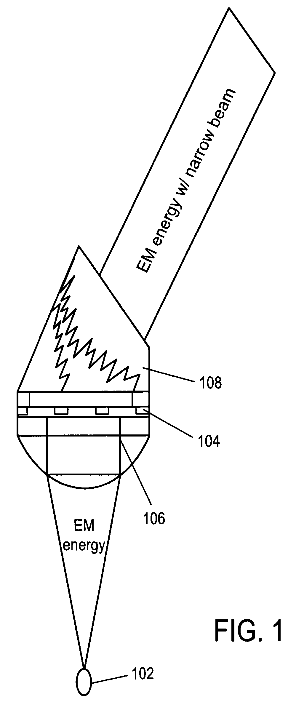
[0021]FIG. 1 illustrates an exemplary apparatus 100, such as an antenna, for emitting electromagnetic (EM) energy. The apparatus comprises a source of EM energy 102. A first material, such as an input dielectric layer 106, is provided to transmit incident EM energy emitted from the EM source. The first material is thus configured (e.g., shaped, sized and positioned relative to the EM source and to other components of the apparatus 100) to receive EM energy from the EM source. The input dielectric layer 106 can be a collimator such as a Duroid, on other material having similar characteristics.

[0022]A second material, such as a metal layer 104, has a first surface adjacent a second material having a first surface adjacent to the first material and a thickness and shape selected to stimulate surface plasmon polaritons on the first surface of the second material adjacent the first material to resonate the EM energy transmitted from the first material such that the resonated EM energy ha...


PUM


Abstract

Systems and methods are disclosed for emitting electromagnetic (EM) energy. A source emits EM energy that is incident on a first material. The first material transmits EM energy to a second material. The second material can have a first surface adjacent to the first material and a thickness and shape selected to stimulate surface plasmon polaritons on the first surface of the second material to resonate the EM energy transmitted from the first material such that the resonated EM energy has an EM wavelength in a narrow field of view with substantially no sidelobes.

Description

CROSS REFERENCE TO PRIOR APPLICATIONS[0001]This application claims the benefit of priority of provisional application No. 60 / 873,957 filed on Dec. 11, 2006, the entire content of which is hereby incorporated by reference.BACKGROUND[0002]1. Field[0003]Systems and methods are disclosed for emitting electromagnetic (EM) energy.[0004]2. Background Information[0005]Surface plasmon polaritons are surface plasmons associated with incident light waves that result when free space electromagnetic waves couple to free electron oscillations (surface plasmons) in metal. Surface plasmon polaritons are lightwaves trapped on a conductive metal surface due to their interactions with electrons on the conductive metal surface.[0006]Metal supports collective surface oscillations of free electrons. These collective surface oscillations can concentrate electromagnetic fields on the nanoscale, enhancing local field strength in a particular direction by several orders of magnitude. Plasmon characteristics ...

Claims


Application Information

Patent Timeline
Patent Type & Authority Patents(United States)
IPC IPC(8): G01R31/26
CPCG21K1/06G21K1/08H05H6/00G21K2201/067
Inventor SCHROEDER, WAYNE K.TURNER, MARK A.WILLIAMS, BRETT A.
Owner LOCKHEED MARTIN CORP
Why Eureka
Try Eureka