
Guidewire for vascular catheters

a technology for vascular catheters and guide wires, which is applied in the direction of guide wires, catheters, applications, etc., can solve the problems of additional catheters which have to be pushed into the vessel, the display of catheters and organic tissue, and the inability to achieve an improvement in visibility, etc., and achieves the effect of convenient positioning

Inactive Publication Date: 2010-10-26
SIEMENS HEALTHCARE GMBH
View PDF25 Cites 53 Cited by
  • Summary
  • Abstract
  • Description
  • Claims
  • Application Information

AI Technical Summary

Benefits of technology

The invention is a guidewire designed to be easily positioned in the body for medical procedures. It uses electromagnetic technology to accurately locate the guidewire and can be calibrated using x-ray images. The guidewire is designed to be flexible and easily moved, and it can be navigated using external magnetic fields. The guidewire can also have a slide coating to make it easier to move catheters. The invention also includes a processing device that records the field line curves of the navigation magnet system to improve accuracy. The guidewire can be made with individual strands woven together, and it can have additional ultrasonic sensors in the tip for better positioning. Overall, the invention provides a simple and precise way to position a guidewire for medical procedures.

Problems solved by technology

The disadvantage of this method is that only the vessel diameter and / or the narrowing which can be used by the blood flow is displayed here as a two-dimensional silhouette.
The disadvantage with this method is that the guidewire, catheter and organic tissue are displayed with different qualities in the x-ray image.
U.S. Pat. No. 5,365,943 describes an anatomically adjusted maneuverable PTKA guidewire which can be inserted easily but does not achieve an improvement in the visibility.
The disadvantage of this method lies in the additional catheter which has to be pushed into the vessel in order to obtain these photos.
Furthermore, this solution is disadvantageous in that the human body is assumed as the model of an endless, homogenous, conductible half-space and that additionally the measuring device has to be positioned in a shielding chamber.
Nevertheless this system is also a catheter which is moreover equipped with relatively expensive sensors.
The main disadvantage of this device is that in this case it is not a guidewire which can be used for a multiplicity of medical aids, but is instead a special catheter which is inserted into the body and only allows special medical applications and must be withdrawn from the body when the medical aid is changed.

Method used


Image

  • Guidewire for vascular catheters
  • Guidewire for vascular catheters
  • Guidewire for vascular catheters

Examples


Embodiment Construction

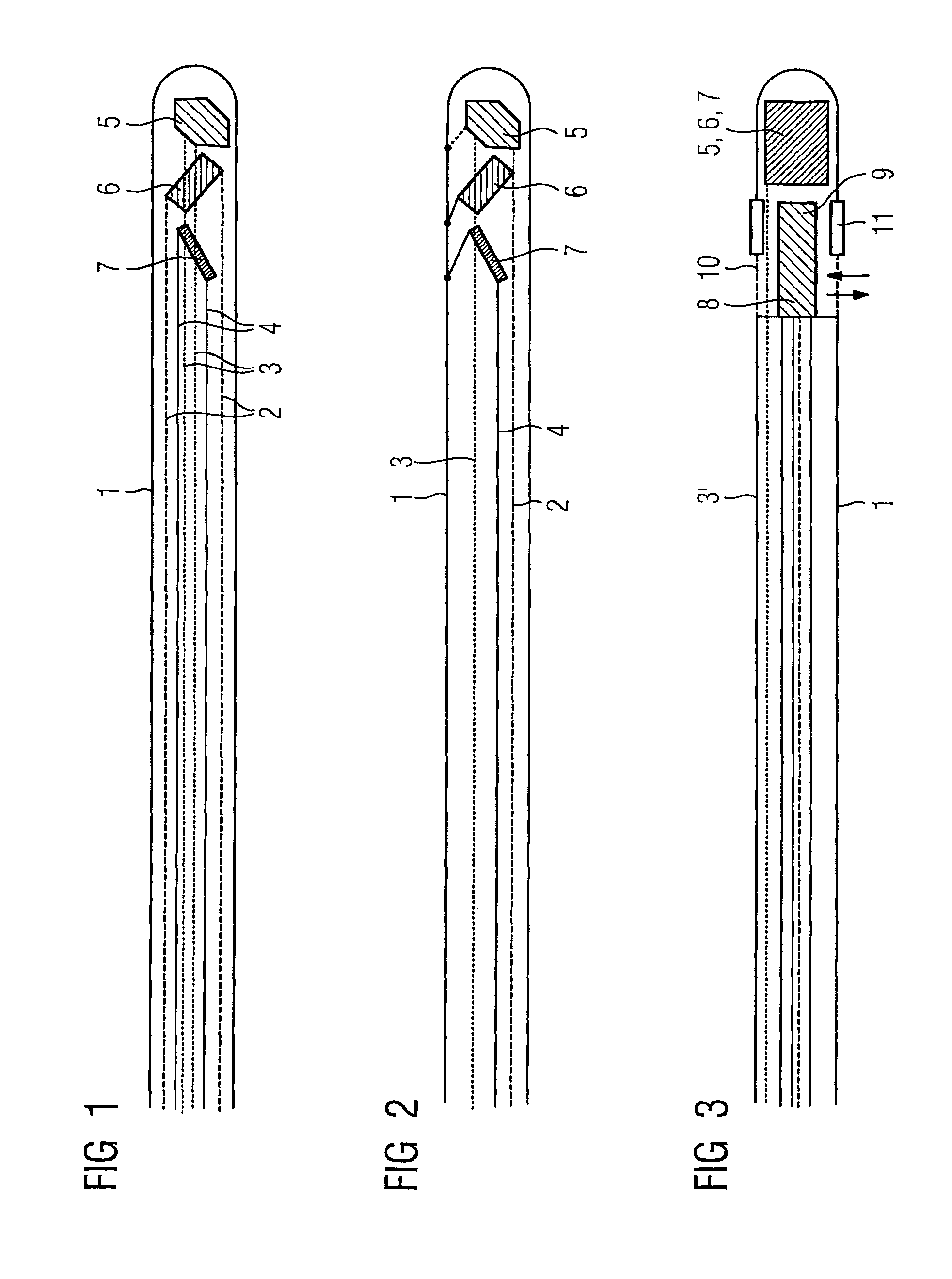
[0036]The guidewire with an external guidewire housing 1 illustrated schematically in FIG. 1 contains paired signal lines 2, 3, and 4 at receive coils 5, 6 and 7 aligned to the x-, y- and z-direction. Contrastingly, with the exemplary embodiment according to FIG. 2, the receive coils 5, 6, and 7 are linked on the one side to the external guidewire housing 1, so that only one signal line is to be recirculated to each receive coil which is preferably embodied as an insulated individual strand which is woven together to the guidewire using further individual strands.

[0037]In addition to the receive coils 5 to 7 illustrated in FIGS. 1 and 2, which are only shown as small boxes in FIG. 3 with the signal lines deriving therefrom not being shown in any more detail, but instead only with reference to a schematically indicated signal line 3, the guidewire according to FIG. 3 additionally features an OCT sensor 8 and an IVUS sensor 9 which are arranged respectively within an OCT viewing windo...


PUM


Abstract

Guidewire for catheters which can be inserted into cavities, preferably coronary vessels of humans or animals, said guidewire being provided with electromagnetic receive or transmit locate to position its position in conjunction with corresponding external electromagnetic transmit or receive antennas, as well as with signal lines guiding the processing unit controlling the transmit antennas or transmit coils.

Description

CROSS REFERENCE TO RELATED APPLICATIONS[0001]This application claims priority to the German application No. 10 2004 058 008.1, filed Dec. 1, 2004 which is incorporated by reference herein in its entirety.FIELD OF INVENTION[0002]The invention relates to a guidewire for catheters which can be inserted into cavities, preferably coronary vessels, of humans or animals.BACKGROUND OF INVENTION[0003]One of the most common fatal diseases is vascular disease, in particular cardiac infarction. This is caused by diseases of the coronary arteries (arteriosclerosis). With such diseases, deposits (atherosclerotic plaque) cause a ‘blockage’ in the coronary vessels.[0004]A PTCA (Percutaneous transluminal coronary angioplasty) is used nowadays in the majority of cases if the coronary angiography shows severe narrowing (stenoses) of the coronary arteries, which cause angina pectoris, restrict a persons capability and / or endanger his / her life. For this purpose, the narrowings of the coronary vessels ar...

Claims


Application Information

Patent Timeline
Patent Type & Authority Patents(United States)
IPC IPC(8): A61B5/05
CPCA61B5/0066A61B5/06A61B5/6851A61B19/5244A61M25/09A61B8/12A61B2017/22038A61B2019/5251A61B2019/5454A61M2025/0166A61M2025/09183A61B34/20A61B2034/2051A61B2090/3954A61B5/062
Inventor MASCHKE, MICHAELKLINGENBECK-REGN, KLAUS
Owner SIEMENS HEALTHCARE GMBH
Learn More