
Firearm with a detachable barrel and suppressed barrel assembly

a suppressed barrel and barrel technology, applied in the field of suppressed barrel assemblies, can solve the problems of inability to easily remove the barrel, and existing rugerTM pistols do not lend themselves to allowing for the detachable barrel

Inactive Publication Date: 2010-11-02
WHEATLEY CRAIG A
View PDF10 Cites 63 Cited by
  • Summary
  • Abstract
  • Description
  • Claims
  • Application Information

AI Technical Summary

Benefits of technology

[0016]A first unique improvement provided by the invention is an interchangeable barrel receiver that incorporates a feed ramp independent of the presence or absence of an installed barrel. The barrel for the Ruger™ pistols has a feed ramp as part of the barrel rather than as part of the receiver just as other quick detach .22 caliber pistols include a feed ramp as part of the barrel. Incorporating the feed ramp as a part of the receiver results in reduced machining and manufacturing costs when manufacturing multiple interchangeable barrels.
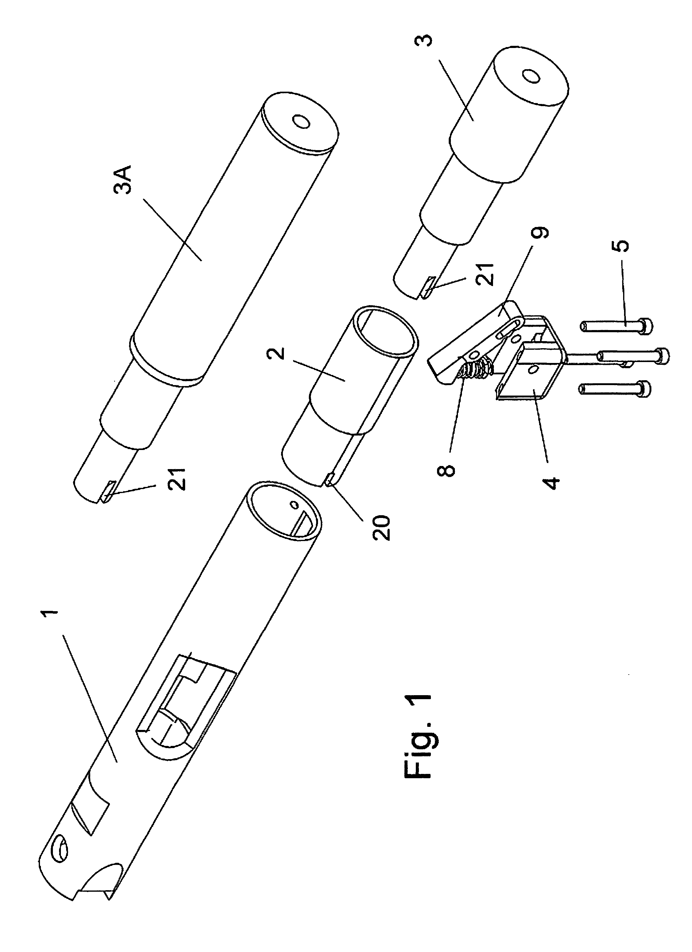
[0018]A third unique improvement is the provision of a quick detach barrel mechanism as part of the receiver. This quick detach mechanism comprises a spring-biased lever or catch that is forced up under pressure from the spring acting upon a shoulder on the bottom of the lever or catch. The lever or catch fits into a cut-out in the barrel or sound suppressed barrel assembly positioned on the bottom of the barrel or sound suppressed barrel assembly. Activation of the quick detach mechanism is achieved by simply pushing the lever or catch upwards against the spring pressure. This allows for the removal of the barrel or sound suppressed barrel assembly from the receiver and insertion of the barrel or sound suppressed barrel assembly into the interchangeable barrel receiver.

Problems solved by technology

These pistols are available in different barrel lengths, but due to the design and construction of these pistols, the barrel is not easily removable and is not intended to be removed by the user.
The main problem is that the barrel attaches to the receiver of the pistol by screw threads, the assembly which is then machined as and into a single combined part, which is the part of the pistol that has the serial number on it.
The existing Ruger™ pistols do not lend themselves easily to allow for a detachable barrel that is able to be easily changed by the user.

Method used


Image

  • Firearm with a detachable barrel and suppressed barrel assembly
  • Firearm with a detachable barrel and suppressed barrel assembly
  • Firearm with a detachable barrel and suppressed barrel assembly

Examples


Embodiment Construction

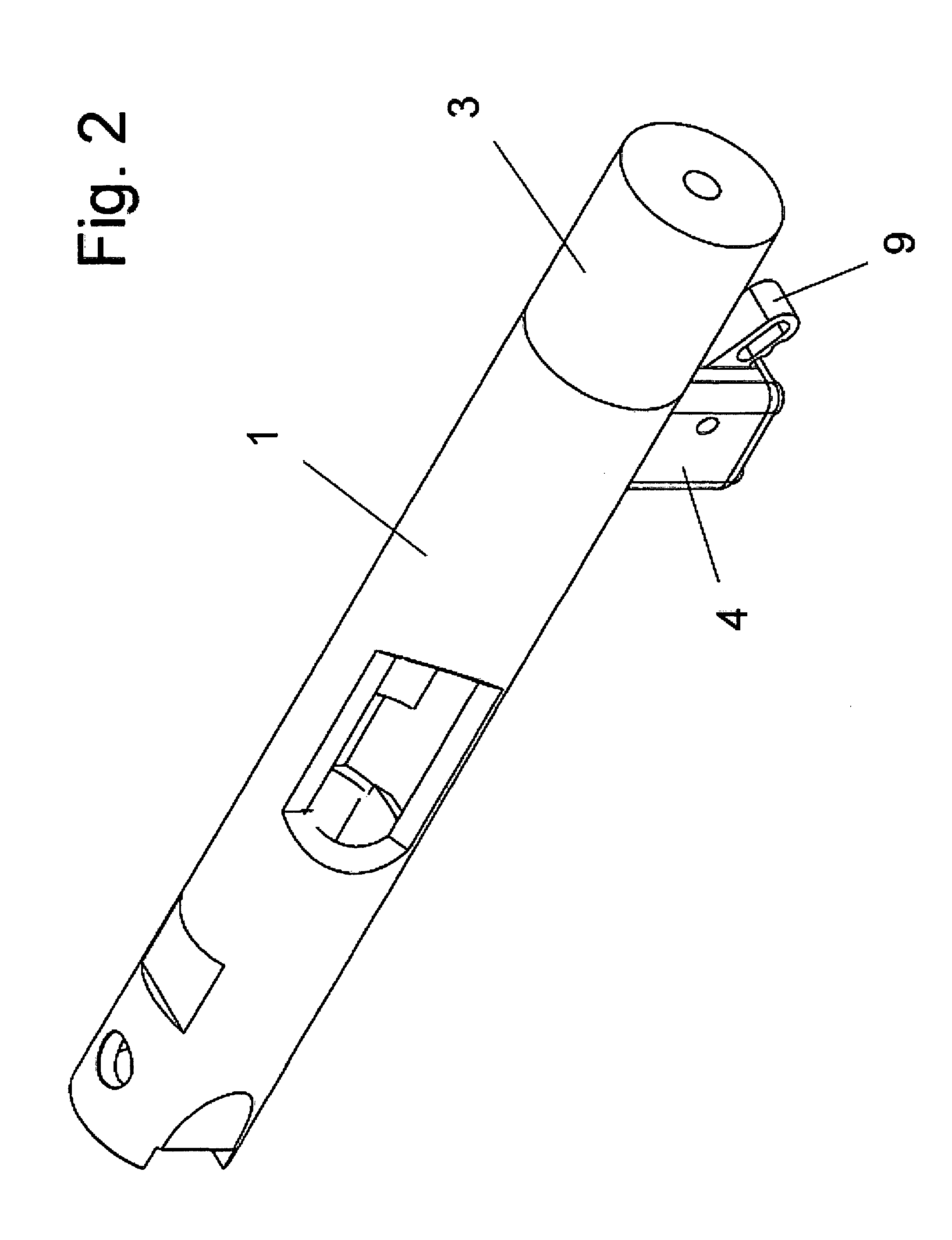
[0031]FIGS. 1 and 2 show an interchangeable barrel receiver that incorporates a quick detach mechanism, a bushing that incorporates a feed ramp, and a quick detach barrel in exploded and assembled perspective views. The interchangeable barrel receiver 1 is of a type similar to that of the Ruger™ Mk I / II / III™ or .22 / 45™ pistols and may replace the existing receiver of a Ruger™ Mk I / II / III™ or .22 / 45™ pistol if so desired, or may form the basis for the receiver of a pistol of similar design and appearance to that of the Ruger™ Mk I / II / III™ or .22 / 45™ pistols. The interchangeable barrel receiver 1 in this instance is extended in length when compared to the receiver of the Ruger™ Mk I / II / III™ or .22 / 45™ pistols to allow for the use of a quick detach mechanism for replacing or changing barrels or it may be of identical length as dictated by mating parts compatibility. A bushing 2 is secured to the interchangeable barrel receiver. The bushing 2 is machined internally to allow for insertio...


PUM


Abstract

A semi-automatic pistol with a detachable barrel and / or a detachable suppressed barrel assembly consists of a new or replacement interchangeable barrel receiver of a type similar to that of the Ruger™ Mk I / II / III or .22 / 45™ pistols with user interchangeable barrels. The interchangeable barrel receiver incorporates a feed ramp and has alignment surfaces that provide positive alignment with the user interchangeable barrel or sound suppressed barrel assembly. Means are provided for allowing the user to change barrels.

Description

BACKGROUND OF THE INVENTION[0001]1. Field of the Invention[0002]This application relates broadly to a firearm, specifically a semi-automatic pistol, and more particularly, it concerns an interchangeable barrel receiver semi-automatic pistol with a (1) detachable barrel and / or (2) a detachable suppressed barrel assembly.[0003]2. Description of the Prior Art[0004]Detachable barrels for semi-automatic pistols, specifically .22 caliber pistols, are well known in the art. Examples of prior art for .22 caliber semi-automatic pistols include the following U.S. Pat. Nos. 2,817,174 (Liedke), 2,958,974 (Sefried II), 3,150,458 (Browning), and 4,109,403 (Badali). One of the most popular .22 caliber semi-automatic pistols is made by Ruger™ and has been made since 1949 in a number of models. These are known as the Ruger™ Mk I / II / III™ and .22 / 45™ pistols. These pistols are available in different barrel lengths, but due to the design and construction of these pistols, the barrel is not easily remov...

Claims


Application Information

Patent Timeline
Patent Type & Authority Patents(United States)
IPC IPC(8): F41A21/48
CPCF41A3/66F41A21/484
Inventor WHEATLEY, CRAIG A.
Owner WHEATLEY CRAIG A
Learn More