Yellow light emitting device with high luminance

a light emitting device and yellow light technology, applied in the direction of discharge tube luminescnet screens, discharge tube/lamp details, electric discharge lamps, etc., can solve the problems of short life of fluorescent lamps, high running costs, and inability to design and manufacture signboards at will or at a low cost, and achieve high luminance and high luminance

Active Publication Date: 2010-11-02
NICHIA CORP
View PDF13 Cites 48 Cited by
  • Summary
  • Abstract
  • Description
  • Claims
  • Application Information

AI Technical Summary

Benefits of technology

[0014]The filter preferably transmits light of wavelengths shorter than 480 nm at a rate of about 10% or less when a maximum transmittance to light of wavelengths ranging from 380 nm to 730 nm is taken as 100%. This makes it possible to cut off the light mainly from the light emitting element and provide light emitting device having large values of chromaticity coordinates x, y.
[0015]It is preferable that the mixed light prior to passing the filter has such a mixing ratio as the ratio of an intensity of the light component having a peak emission wavelength of the fluorescent material to an intensity of the light component having a peak emission wavelength of the light emitting element that is about 1.0 or higher and not higher than about 20. This makes it possible to provide the light emitting device having high luminance.
[0016]It is preferable that the mixed light prior to passing the filter includes a light component of peak emission wavelength of the light emitting element and a light component of peak emission wavelength of the fluorescent material, and has a y value of the chromaticity coordinate not lower than about 0.400 on the chromaticity diagram according to CIE 1931. This makes it possible to provide light emitting device having high luminance.

Problems solved by technology

However, the fluorescent lamp has short life which requires frequent replacements and a high running cost.
The fluorescent lamp also has limitations on the size and configuration thereof, which make it impossible to design the signboard at will or manufacture it at a low cost.
The light emitting device which uses yellow color LED currently available is not capable of changing the color tone of the yellow light.
However, it is not easy to control the color tone by this method.
Moreover, there has been no yellow color LED developed for practical use which can emit light with a level of luminance high enough for use in a signboard.
However, since the light emitting device of this type mixes blue light and yellow light, the resultant light tends to have whitish yellow color.
A large amount of the type A3B5O12 fluorescent material disposed in a very high density causes such a problem that yellow light emitted by the type A3B5O12 fluorescent material is blocked by other particles of the type A3B5O12 fluorescent material and it becomes difficult to take out light from the light emitting device in the output direction.
As a result, although the light emitting device emits yellow light, the luminance of emission is low and yellow light emitting device of high luminance cannot be obtained.

Method used


Image

  • Yellow light emitting device with high luminance
  • Yellow light emitting device with high luminance
  • Yellow light emitting device with high luminance

Examples


embodiments

Light Emitting Device

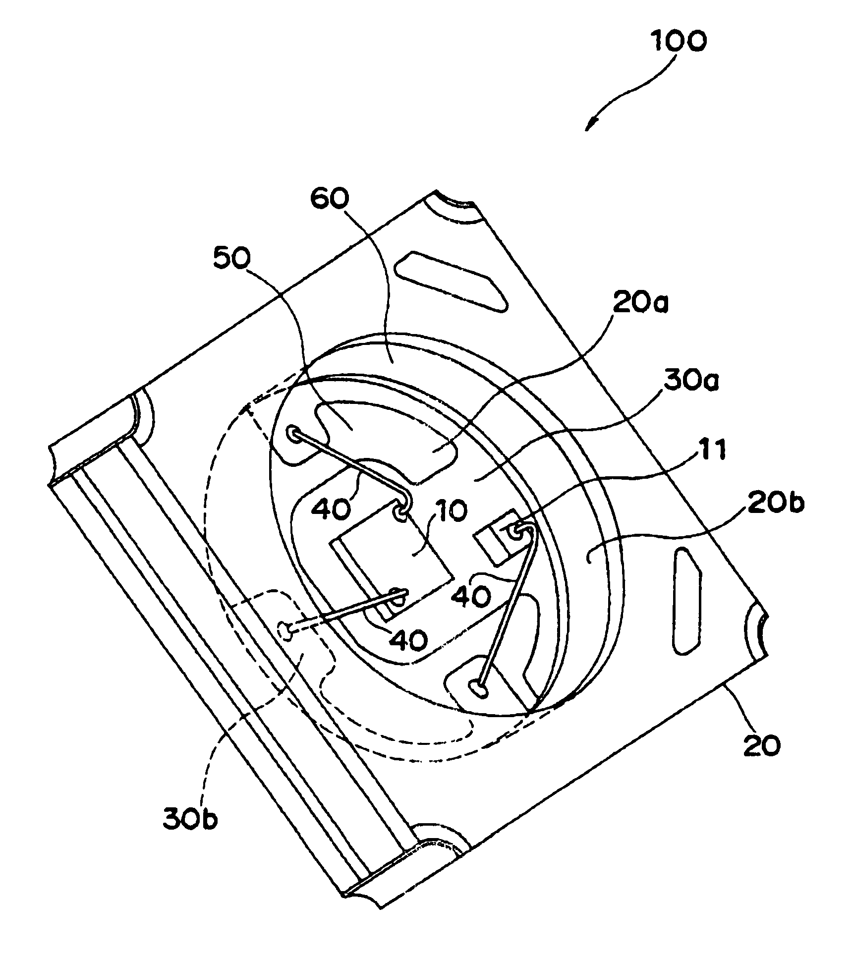
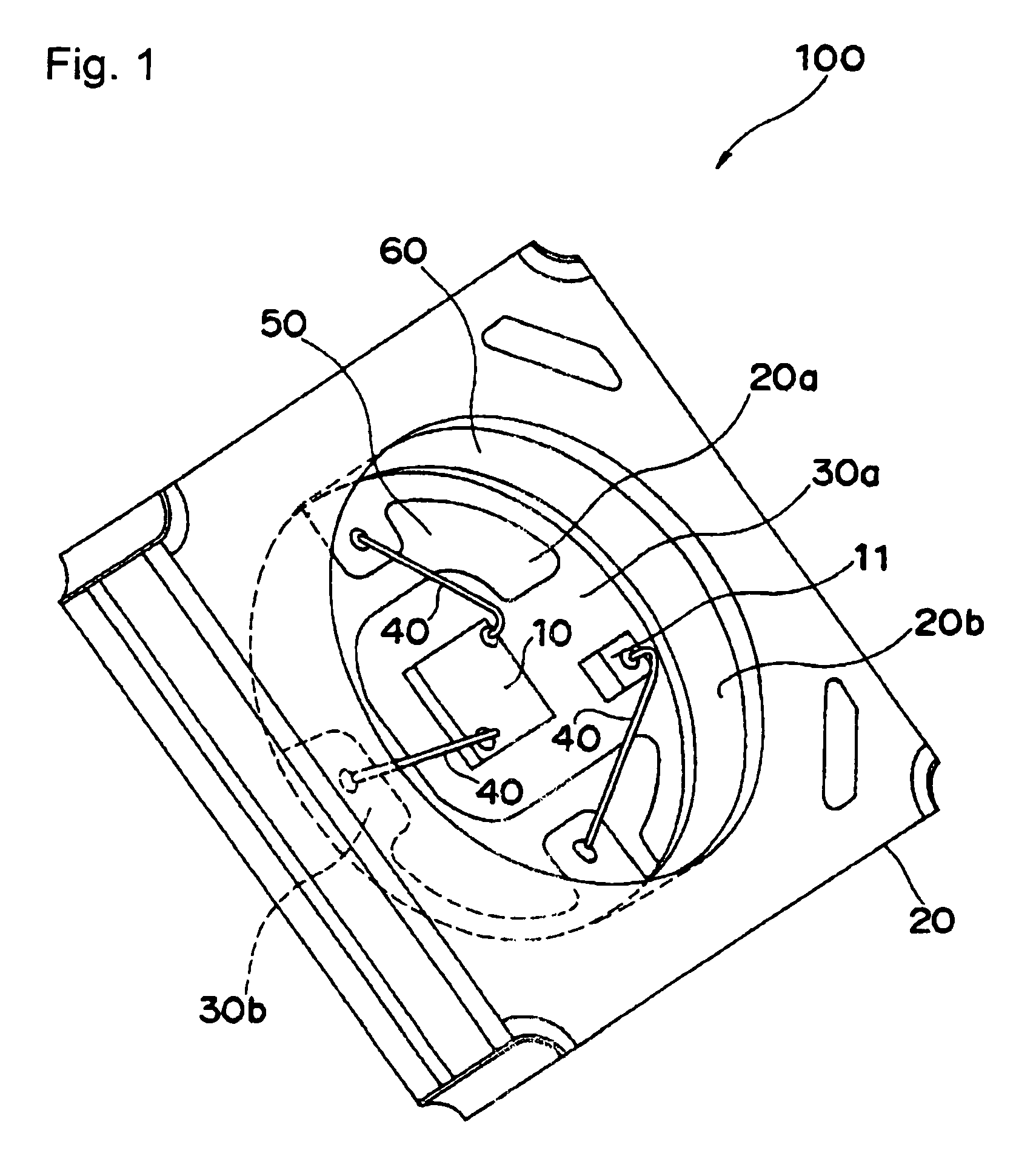
[0049]A light emitting device 100 according to the embodiment comprises a light emitting element 10 serving as the excitation light source, a package 20 having a recess, a fluorescent material 50 and a filter (not shown).

[0050]The recess of the package 20 has a bottom surface 20a on which the light emitting element 10 is placed and a side surface 20b extending from the bottom surface 20a. A first electrode 30a and a second electrode 30b are provided on the bottom surface 20a of the recess of the package 20. The first electrode 30a and the second electrode 30b make a pair of positive and negative electrodes. The first electrode 30a continues to a corner and a back surface of the outside of the package 20 and is electrically connected to an external electrode at the corner and the back surface. The second electrode 30b similarly continues to other corner and the back surface of the outside of the package 20 and is electrically connected to an external electrode at...

example 1

[0082]The present invention will now be described by way of examples. The light emitting device used in examples is that described in relation to the embodiment. FIG. 1 is a perspective view schematically showing the light emitting device of Examples 1 to 29.

[0083]FIG. 3 shows the transmittance of the filter used in Examples 1 to 29. Transmittance is given in terms of a value relative to the transmittance of the filter at 730 nm which is assumed to be 100%. The filter cuts off the light of wavelengths shorter than 480 nm with transmittance of 10% or less.

examples 1 to 7

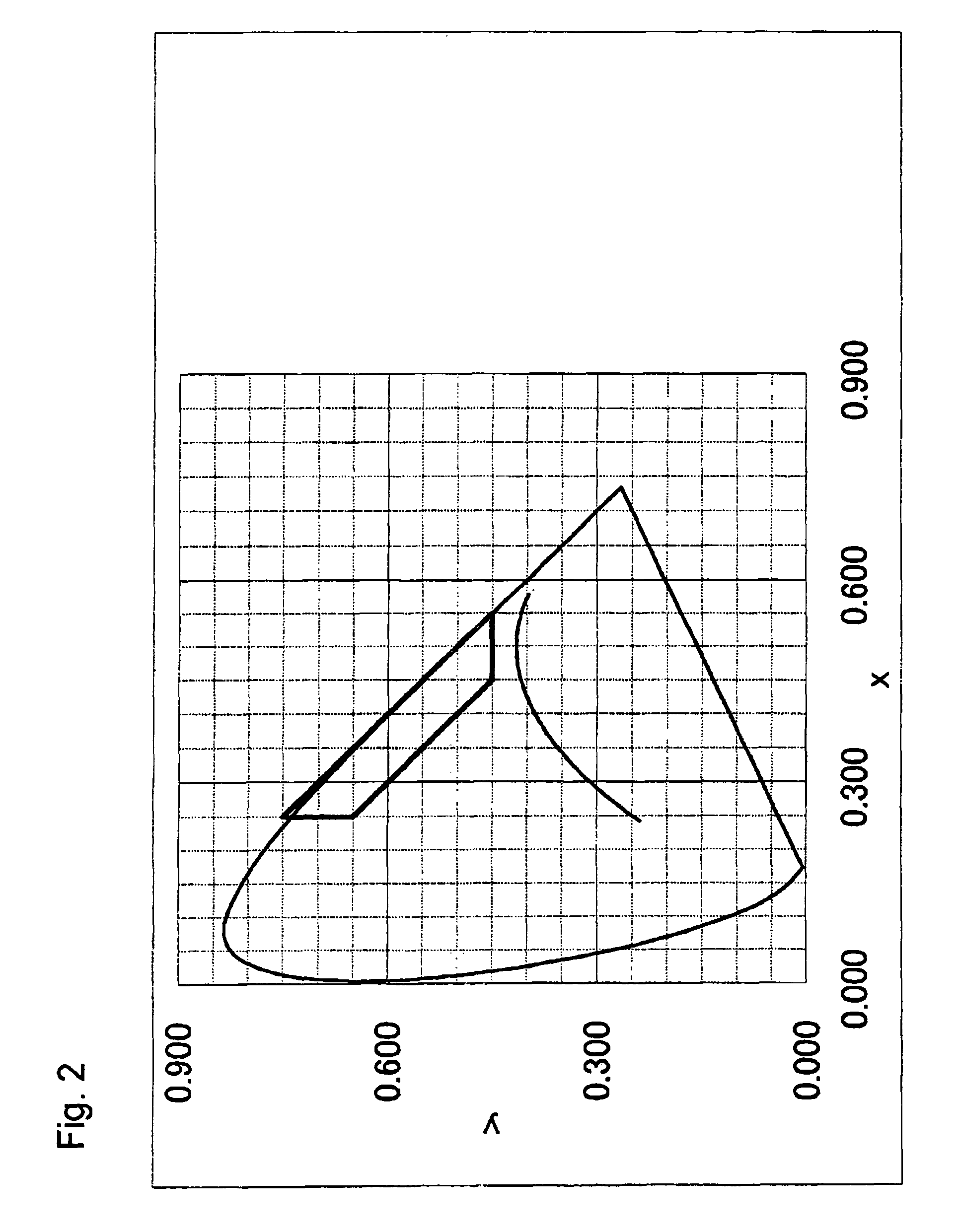
[0084]The light emitting device according to Examples 1 to 7 will now be described. FIG. 4 shows an emission spectrum of (Y, Gd)3Al5O12 fluorescent material excited by light having wavelength of 450 nm. FIGS. 5A and 5B show emission spectra of the fluorescent material excited by light from the light emitting element according to Examples 1 to 7 (before passing the filter). FIG. 6 shows chromaticity coordinates (CIE 1931) of light from the fluorescent material excited by light from the light emitting element according to Examples 1 to 7 (before passing the filter). FIG. 7 shows chromaticity coordinates (CIE 1931) of light from the light emitting device according to Examples 1 to 7.

[0085]The light emitting device 100 according to Examples 1 to 7 comprises the light emitting element 10, the package 20 having the recess consisting of the bottom surface 20a on which the light emitting element 10 is placed and the side surface 20b extending from the bottom surface 20a, the fluorescent mat...


PUM


Abstract

An object of the present invention is to provide a light emitting device which emits light of deep yellowish color with high luminance. The light emitting device of the present invention comprises a light emitting element having a peak emission wavelength shorter than 490 nm, a fluorescent material for wavelength conversion which absorbs light from the light emitting element and emits light of a wavelength longer than that of the light from the light emitting element, and a filter which cuts off a part of a mixed light produced by mixing the light of the light emitting element and the light of the fluorescent material, wherein the light transmitted through the filter has a chromaticity coordinate on the chromaticity diagram according to CIE 1931 plotted in a region defined by a first point (x=0.450, y=0.450), a second point (x=0.250, y=0.650), a third point (x=0.350, y=0.750) and a fourth point (x=0.250, y=0.750) and in the region defined by a closed curve consisting of the monochromatic locus and the purple boundary.

Description

BACKGROUND OF THE INVENTION[0001]1. Field of the Invention[0002]The present invention relates to a light emitting device which emits yellowish light, for example, a light emitting device used as a backlight for liquid crystal display and other displays.[0003]2. Description of the Related Art[0004]There is demand for a light emitting device which emits yellow light for such applications as signals, illuminations and signboards.[0005]The light source for a Signboard is currently a fluorescent lamp which is inexpensive and high emission efficiency. However, the fluorescent lamp has short life which requires frequent replacements and a high running cost. The fluorescent lamp also has limitations on the size and configuration thereof, which make it impossible to design the signboard at will or manufacture it at a low cost. Also from the view point of environment, it is called for to use a light source which does not involve mercury. With this background, much attention is focused on a li...

Claims


Application Information

Patent Timeline
Patent Type & Authority Patents(United States)
IPC IPC(8): H01J1/62H01J63/04H01L33/50H01L33/60H01L33/62
CPCH01L33/44H01L33/502H01L2224/48091H01L2924/00014H01L2224/48247H01L2224/48465H01L2924/00H01L25/167
Inventor TAKASHIMA, SUGURUAIHARA, MASATOKISHIMOTO, TOMOHISAMIKI, HITOMIAOYAGI, KENICHIKIHARA, TAKESHI
Owner NICHIA CORP
Why Eureka
Try Eureka