Control system for plant

a control system and plant technology, applied in the field of plant control system, can solve the problems of large size, reduced control stability, and insufficient control system to deal with the change in the dynamic characteristic of the controlled object, and achieve the effect of sufficient robustness and stability

Inactive Publication Date: 2010-11-02
HONDA MOTOR CO LTD
View PDF8 Cites 3 Cited by
  • Summary
  • Abstract
  • Description
  • Claims
  • Application Information

AI Technical Summary

Benefits of technology

[0008]The present invention was made contemplating the above-described points, and an object of the present invention is to provide a control system for a plant, which performs the sliding mode control with sufficient robustness and stability when the change in the dynamic characteristic of the controlled object is comparatively great, the disturbance is comparatively great, and / or the controlled object has nonlinear characteristics.
[0010]With this configuration, the transfer characteristic of the transfer characteristic adjusting means is set so that the composite transfer function indicative of the transfer characteristic which is obtained by combining the transfer characteristic of the transfer characteristic adjusting means and the transfer characteristic of the controlled object model, coincides with the desired target transfer function. Accordingly, by appropriately setting the target transfer function and controlling the extended controlled object having the transfer characteristic expressed by the target transfer function with the sliding mode control, the sliding mode control with sufficient robustness and stability can be performed even when such an error factor that the change in the dynamic characteristic of the controlled object is comparatively great, the disturbance is comparatively great, and / or the controlled object has nonlinear characteristics, exists.
[0012]With this configuration, the difference between the feedback control input calculated with the sliding mode control and the controlled output of the plant, is calculated, and the control input to the plant is calculated by applying the frequency shaping transfer function to the difference. Accordingly, an extended controlled object having a transfer characteristic expressed by the target transfer function becomes the controlled object of the sliding mode control, which makes it possible to always perform the sliding mode control with sufficient robustness and stability.
[0014]With this configuration, the disturbance component applied to the plant is estimated according to the control input to the plant and the controlled output of the plant, and the control input to the plant is calculated by subtracting the estimated disturbance component from the feedback control input. An extended controlled object having a transfer characteristic expressed by the target transfer function becomes the controlled object of the sliding mode control, which makes it possible to always perform the sliding mode control with sufficient robustness and stability.
[0016]With this configuration, the difference between the feedback control input and the controlled output of the plant is calculated, and the frequency shaped output is calculated by applying the frequency shaping transfer function to the calculated difference. The disturbance component applied to the plant is calculated according to the control input to the plant and the controlled output of the plant, and the control input to the plant is calculated by subtracting the estimated disturbance component from the frequency shaped output. According to the above-described calculation, the extended controlled object having a transfer characteristic expressed by the target transfer function becomes a controlled object of the sliding mode control, which makes it possible to always perform the sliding mode control with sufficient robustness and stability. Further, addition of the frequency shaping controller and the disturbance estimating means makes it possible to increase flexibility in designing the control system. For example, the response characteristic of the control can be adjusted with the calculation of the frequency shaped output, and robustness and stability of the control can be secured with subtraction of the disturbance component when there is an error factor.
[0018]With this configuration, the band-pass filtering of the estimated disturbance component is performed, and the filtered disturbance component is applied to the calculation of the control input. Noise components are removed by the band-pass filtering, which makes it possible to prevent a drawback such that the controlled output vibrates in a small amplitude.

Problems solved by technology

However, if the change in the dynamic characteristic is comparatively large, disturbance applied to the controlled object is comparatively large, or the controlled object has nonlinear characteristics, a modeling error (a difference between the characteristic of an actual controlled object and the characteristic of the controlled object model) temporarily becomes large, and control stability may be reduced.
Accordingly, there is a possibility that the control system can not sufficiently deal with the change in the dynamic characteristic of the controlled object.

Method used


Image

  • Control system for plant
  • Control system for plant
  • Control system for plant

Examples


first embodiment

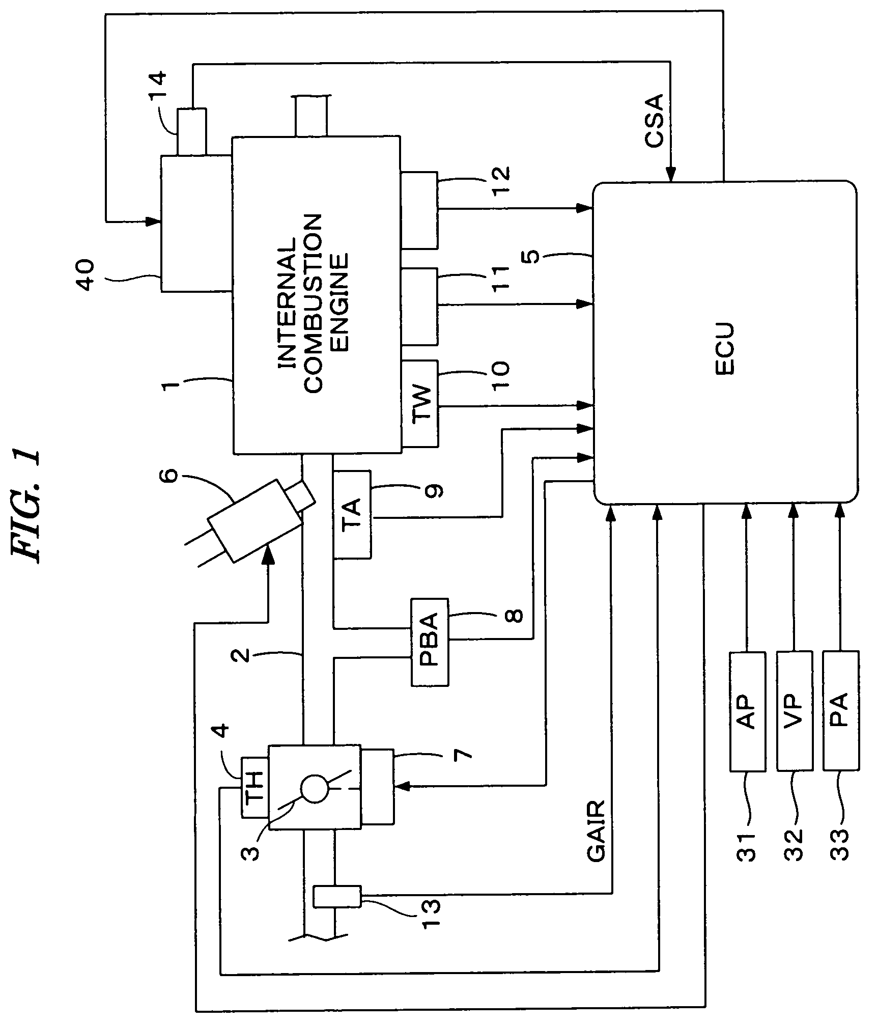
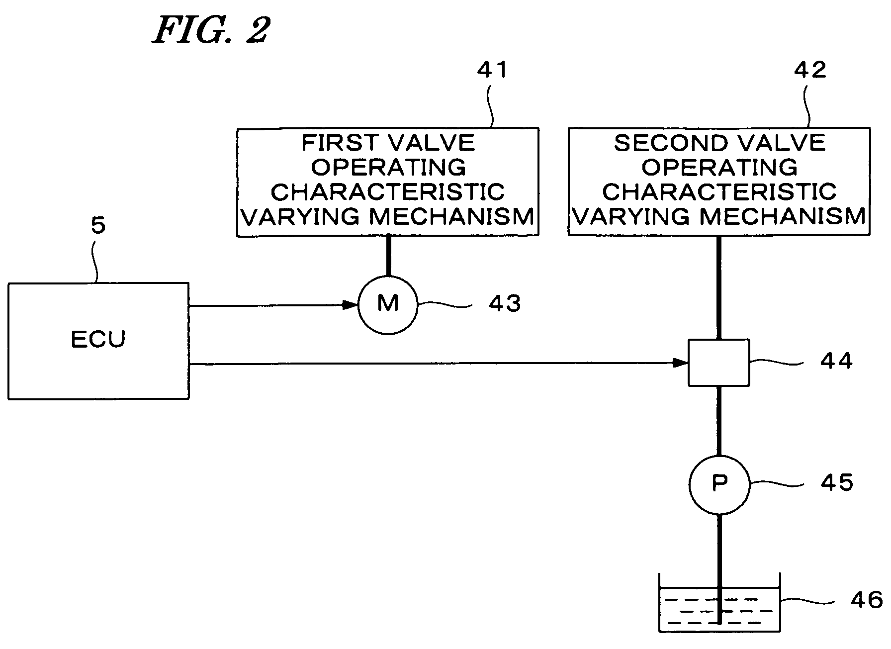
[0039]FIG. 1 is a schematic diagram showing a configuration of an internal combustion engine and a control system therefor according to a first embodiment of the present invention. FIG. 2 is a schematic diagram showing a configuration of a valve operating characteristic varying device.

[0040]Referring to FIG. 1, an internal combustion engine (hereinafter referred to as “engine”) 1, having, for example, four cylinders can be provided with intake valves and exhaust valves, and cams for driving the intake valves and the exhaust valves. The engine 1 is provided with a valve operating characteristic varying device 40 having a first valve operating characteristic varying mechanism 41 and a second valve operating characteristic varying mechanism 42. The first valve operating characteristic varying mechanism 41 can continuously vary the valve lift amount and the opening angle or valve opening period of the intake valve. The second valve operating characteristic varying mechanism 42 is a cam ...

second embodiment

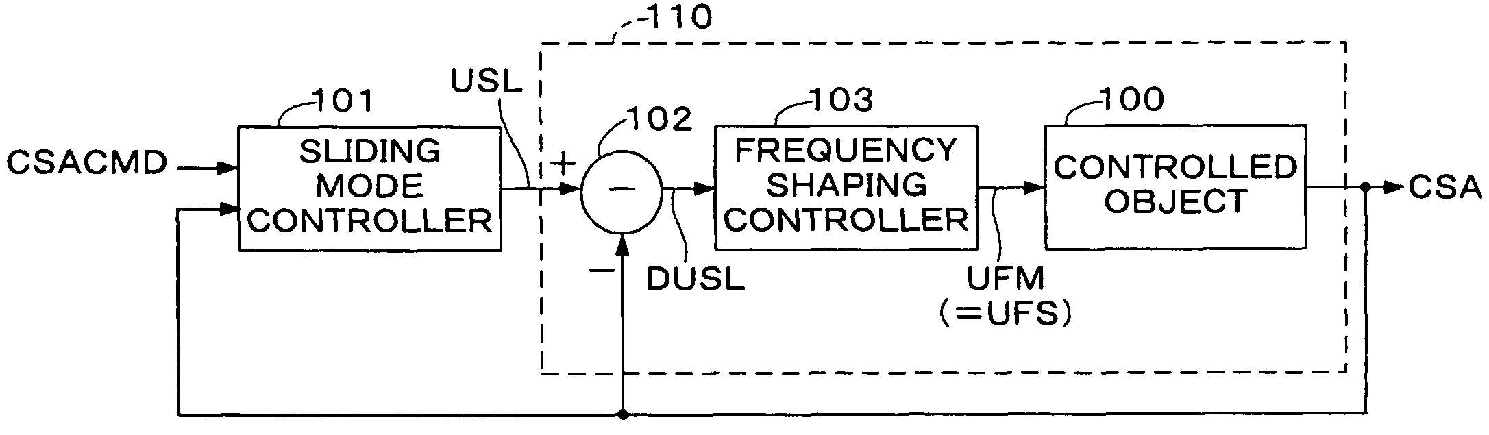
[0088]FIG. 9 is a block diagram showing a configuration of a control system according to a second embodiment of the present invention. The control system shown in FIG. 9 is obtained by deleting the subtractor 102 and the frequency shaping controller 103 of the control system shown in FIG. 5, and adding a disturbance observer 104. The sliding mode controller 101 and the controlled object 100 are the same as those in the first embodiment.

[0089]The disturbance observer 104, as shown in FIG. 10, can include a inverse transfer function block 120, low-pass filters (hereinafter referred to as “LPF”) 121 and 123, and subtractors 122 and 124.

[0090]The inverse transfer function block 120 can perform a calculation which corresponds to an inverse transfer function F−1(s) of the target transfer function F(s) with respect to the CS angle CSA, to calculate a converted control input UFMI. A first LPF121 eliminates high-frequency components in the converted control input UFMI, and outputs a filtered...

third embodiment

[0115]FIG. 12 is a block diagram showing a configuration of a control system in this embodiment. The control system shown in FIG. 12 is configured by inserting a subtractor 102, a frequency shaping controller 103a, and a disturbance observer 104 between the sliding mode controller 101 and the controlled object 100. The sliding mode controller 101 and the controlled object 100 are the same as those of the first embodiment.

[0116]The disturbance observer 104 is configured as shown in FIG. 10 similarly to the second embodiment. It is to be noted that the input parameter of the disturbance observer 104 is changed from the feedback control input USL in the second embodiment to the frequency shaping control input UFS.

[0117]The frequency shaping controller 103a can be configured similarly to the first embodiment by replacing the transfer function G(s) of the controlled object 100 in the first embodiment with the target transfer function F(s) (the composite transfer function of the disturban...


PUM


Abstract

A control system for a plant, including a sliding mode controller and a transfer characteristic adjusting module. The sliding mode controller calculates a feedback control input with a sliding mode control so that an controlled output of the plant coincides with a target value. The transfer characteristic adjusting module is connected to an output of the sliding mode controller, and has a transfer characteristic set according to a transfer function of a controlled object model which is obtained by modeling the plant. A control input to the plant is set to an output of the transfer characteristic adjusting module. The transfer characteristic of the transfer characteristic adjusting module is set so that a composite transfer function indicative of a transfer characteristic which is obtained by combining the transfer characteristic of the transfer characteristic adjusting module and a transfer characteristic of the controlled object model, coincides with a desired target transfer function.

Description

BACKGROUND OF THE INVENTION[0001]1. Field of the Invention[0002]The present invention relates to a control system for a plant, and particularly to a control system that controls a plant with the sliding mode control so that a controlled output of the plant coincide with a target value.[0003]2. Description of the Related Art[0004]Japanese Patent Laid-open No. 2003-15703 (JP '703) discloses a control system which performs a feedback control with the sliding mode control. According to this control system, a feedback control is performed with the sliding mode control so that an opening of a throttle valve of an internal combustion engine coincides with a target opening, for example.[0005]In the above conventional control system, a model parameter identifier is used in order to deal with a change in the dynamic characteristic of the controlled object, and model parameters of a controlled object model which is obtained by modeling the controlled object are identified in real-time processi...

Claims


Application Information

Patent Timeline
Patent Type & Authority Patents(United States)
IPC IPC(8): F02D31/00G06F19/00
CPCF01L13/0063F02D13/02F02D23/00F02D41/1403G05B13/045F01L1/185F01L2013/0068F01L2710/00F01L2800/00F02D2041/1419F02D2041/1433Y02T10/144Y02T10/18Y02T10/12
Inventor IDE, HIROHITO
Owner HONDA MOTOR CO LTD
Why Eureka
Try Eureka