
Composite ePTFE/textile prosthesis

a technology of textile prosthesis and composite material, which is applied in the field of composite multi-layer implantable structure, can solve the problems of increasing the thickness of the tubular structure, affecting the implantation process, so as to improve the ingrowth of tissue, reduce the thickness of the textile layer, and improve the effect of tissue ingrowth

Inactive Publication Date: 2010-11-09
LIFESHIELD SCI
View PDF55 Cites 39 Cited by
  • Summary
  • Abstract
  • Description
  • Claims
  • Application Information

AI Technical Summary

Benefits of technology

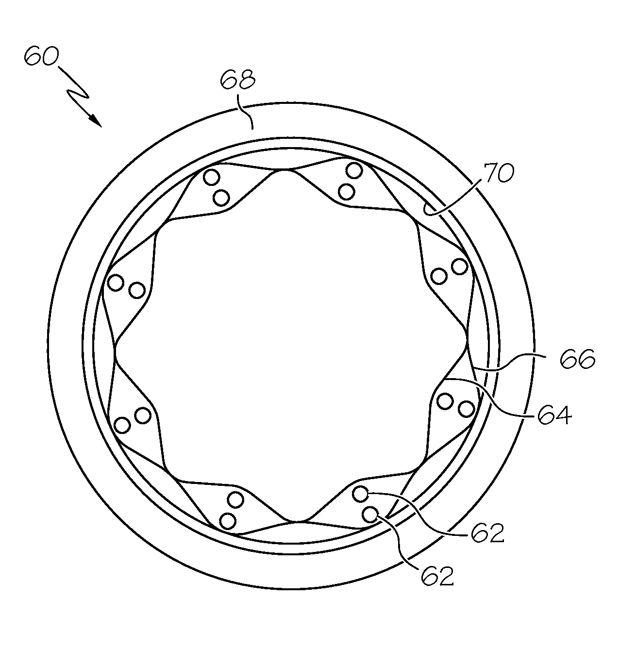
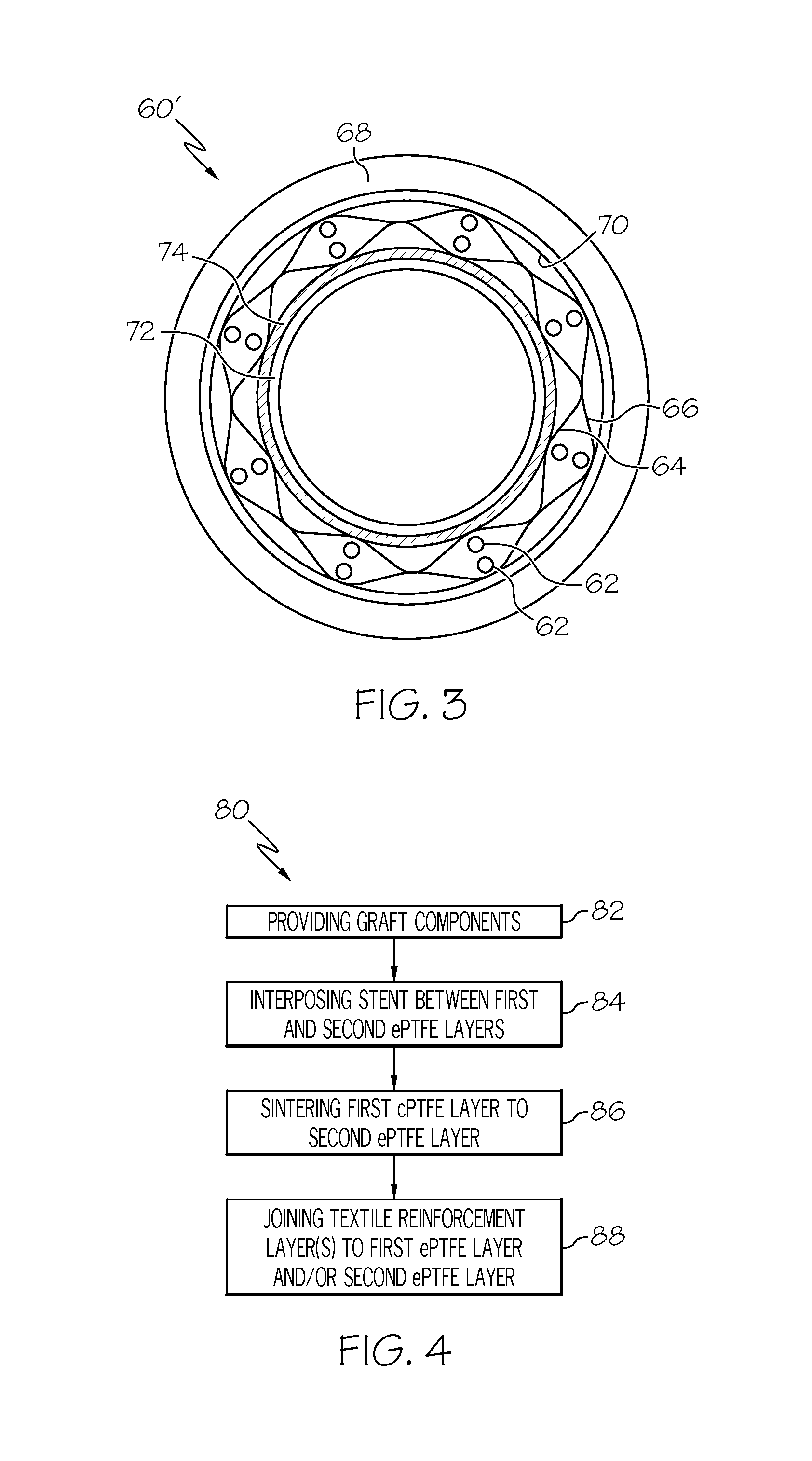
[0016]In another embodiment, the composite multi-layered implantable structure of the present invention may have a first inner tubular layer and a second outer tubular layer, both formed of ePTFE having a porous microstructure defined by nodes interconnected by fibrils. The first and second layers of ePTFE also preferably have a support structure positioned therebetween. Typically, this support structure takes the form of a radially expandable member, preferably a stent. A third tubular layer formed of textile material is circumferentially disposed exteriorly to the first and second layers, and an elastomeric bonding agent is applied to the second layer of ePTFE or the textile layer, and disposed within the pores of the ePTFE microstructure when the layers are bonded together. The bonding agent helps secure the second outer layer of ePTFE to the third textile layer.
[0022]The present invention also provides an ePTFE-lined textile graft. The lined textile graft includes a tubular textile substrate bonded using a biocompatible elastomeric material to a tubular liner of ePTFE. A coating of an elastomeric bonding agent may be applied to the surface of the ePTFE liner so that the bonding agent is present in the micropores thereof. The coated liner is then secured to the tubular textile structure via the elastomeric bonding agent. The liner and textile graft can each be made very thin and still maintain the advantages of both types of materials.
[0025]The composite multi-layered implantable structures of the present invention are designed to take advantage of the inherent beneficial properties of the materials forming each of the layers. The textile layer provides for enhanced tissue ingrowth, high suture retention strength and longitudinal compliance for ease of implantation. The ePTFE layer provides the beneficial properties of sealing the textile layer without need for coating the textile layer with a sealant such as collagen. The sealing properties of the ePTFE layer allow the wall thickness of the textile layer to be minimized. Further, the ePTFE layer exhibits enhanced thrombo-resistance upon implantation. Moreover, the elastomeric bonding agent not only provides for an integral composite structure, but adds further puncture-sealing characteristics to the final prosthesis.

Problems solved by technology

While grafts formed in this manner overcome certain disadvantages inherent in attempts to balance porosity and fluid tightness, these textile prostheses may exhibit certain undesirable characteristics.
These characteristics may include an undesirable increase in the thickness of the tubular structure, which makes implantation more difficult.
These textile tubes may also be subject to kinking, bending, twisting or collapsing during handling.
Moreover, application of a coating may render the grafts less desirable to handle from a tactility point of view.
Grafts formed of ePTFE tend to be relatively non-compliant as compared with textile grafts and natural vessels.
Further, while exhibiting a high degree of tensile strength, ePTFE grafts are susceptible to tearing.
Additionally, PTFE grafts lack the suture compliance of coated textile grafts.
This may cause undesirable bleeding at the suture hole.
Thus, the ePTFE grafts lack many of the advantageous properties of certain textile grafts.
It is also known that it is extremely difficult to join PTFE and ePTFE to other materials via adhesives or bonding agents due to its natural hydrophobic character.
Wetting of the surface by the adhesive is necessary to achieve adhesive bonding, and PTFE and ePTFE are extremely difficult to wet without destroying the chemical properties of the polymer.
Thus, heretofore, attempts to bond ePTFE to other dissimilar materials such as textiles, has been difficult.

Method used


Image

  • Composite ePTFE/textile prosthesis
  • Composite ePTFE/textile prosthesis
  • Composite ePTFE/textile prosthesis

Examples


Embodiment Construction

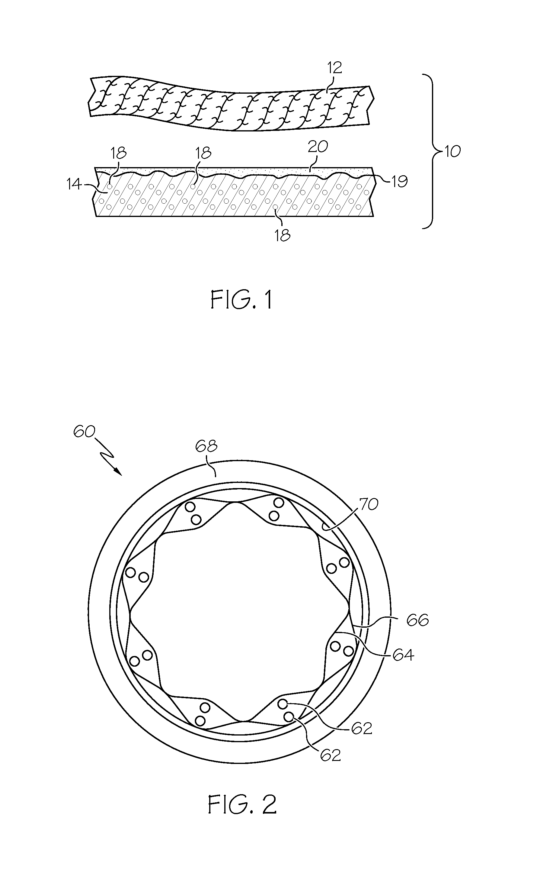
[0033]The present invention provides a composite implantable prosthesis, desirably a vascular prosthesis including two layers of ePTFE surrounding a stent, and a layer of a textile material. The ePTFE stent / graft layers are secured together, with the textile layer, by an elastomeric bonding agent. The vascular prosthesis of the present invention may include a ePTFE-lined textile vascular graft, an ePTFE vascular graft including a textile covering and a composite ePTFE / textile vascular patch.

[0034]Referring to FIG. 1, a schematic cross-section of a portion of a representative vascular prosthesis 10 is shown. As noted above, the prosthesis 10 may be a portion of a graft, patch or any other implantable structure.

[0035]The prosthesis 10 includes a first layer 12 which is formed of a textile material. The textile material 12 of the present invention may be formed from synthetic yarns that may be flat, shaped, twisted, textured, pre-shrunk or un-shrunk. Preferably, the yarns are made from...


PUM

PropertyMeasurementUnit
thicknessaaaaaaaaaa
wall thicknessaaaaaaaaaa

Abstract

A composite intraluminal prosthesis which is preferably used as a vascular prosthesis includes a layer of ePTFE and a layer of textile material which are secured together by an elastomeric bonding agent. The ePTFE layer includes a porous microstructure defined by nodes interconnected by fibrils. The adhesive bonding agent is preferably applied in solution so that the bonding agent enters the pores of the microstructure of the ePTFE. This helps secure the textile layer to the ePTFE layer.

Description

CROSS-REFERENCE TO RELATED APPLICATION[0001]The present application claims priority to U.S. Provisional Application No. 60 / 297,401-Jul. 11, 2001. The present application is being concurrently filed with 10 / 167,676, claiming priority to the same application, and herein incorporated by reference.FIELD OF THE INVENTION[0002]The present invention relates generally to an implantable prosthesis. More particularly, the present invention relates to a composite multilayer implantable structure having a textile layer, an expanded polytetrafluoroethylene layer (ePTFE) and an elastomeric bonding agent layer within the ePTFE porous layer, which joins the textile and ePTFE layer to form an integral structure.BACKGROUND OF THE INVENTION[0003]Implantable prostheses are commonly used in medical applications. One of the more common prosthetic structures include tubular prostheses which may be used as vascular grafts to replace or repair damaged or diseased blood vessels. To maximize the effectiveness...

Claims


Application Information

Patent Timeline
Patent Type & Authority Patents(United States)
IPC IPC(8): A61F2/06A61L27/16A61L27/18A61L27/48A61L27/50A61L31/04A61L31/12
CPCA61F2/06A61F2/07A61L27/16A61L27/18A61L27/48A61L27/50A61L27/507A61L31/048A61L31/129C08L27/18A61F2002/072A61F2/90A61F2002/075A61F2230/005
Inventor HAVERKOST, PATCHOUINARD, PAULRAKOS, RONALDSOWINSKI, KRZYSZTOF
Owner LIFESHIELD SCI
Learn More