Preferentially varying-density ePTFE structure

a technology of eptfe and polytetrafluoroethylene, which is applied in the field of structures containing expanded polytetrafluoroethylene, can solve the problems of increased pore size, increased porosity, and larger voids in the eptfe material, and achieves enhanced tissue ingrowth, low density, and increased stability of the graft within the human body.

Inactive Publication Date: 2009-02-19
LIFESHIELD SCI
View PDF25 Cites 15 Cited by
  • Summary
  • Abstract
  • Description
  • Claims
  • Application Information

AI Technical Summary

Benefits of technology

[0009]The regions of the vascular graft which have a low density provides sites for enhanced tissue ingrowth as well as cell endothelization. This increases the stability of the graft within the human body. Also, the less dense region is more porous and will allow the passage of liquids such as blood or drugs. The high porosity of the reduced density region of the ePTFE has an increased level and rate of ingrowth of tissue over time. This benefits the vascular graft by acting as an anchoring point for the graft as well as a stent which may be secured thereto. This benefit is especially advantageous to an ePTFE tubular structure which covers a stent where the potential of migration is preferably limited.
[0010]The regions of the vascular graft which have a low density have increased flexibility. Increased flexibility provides resistance to kinking of the vascular graft.
[0011]The characteristics and properties of the regions of the ePTFE structure which have an increased density include increased strength. The increased strength of the ePTFE structure typically provides resistance to propagation of a tear through the ePTFE structure which may result from the piercing of the structure associated with the insertion of a suture through the ePTFE structure. Insertion of a suture through the ePTFE structure may be included in a method for implanting the ePTFE structure in the tissue of a patient. If the region of the graft to be pierced can be identified just prior to the piercing, then other longitudinal regions of the graft may have lower strength requirements and therefore have a reduced density. A further benefit of increased strength of the ePTFE structure is increased durability thereof.
[0012]The different characteristics and properties resulting from the difference in densi...

Problems solved by technology

For example, a decrease in the density within a given structure may result in an increased porosity, i.e., increased pore size, which, in turn, results in larger voids in the ePTFE material.
Decreasing the density of an ePTFE tube, however, may limit other properties of the tube.
For example, decreasing the density of the tube may reduce the overall radial and tensile strength thereof as w...

Method used


Image

  • Preferentially varying-density ePTFE structure
  • Preferentially varying-density ePTFE structure
  • Preferentially varying-density ePTFE structure

Examples


Embodiment Construction

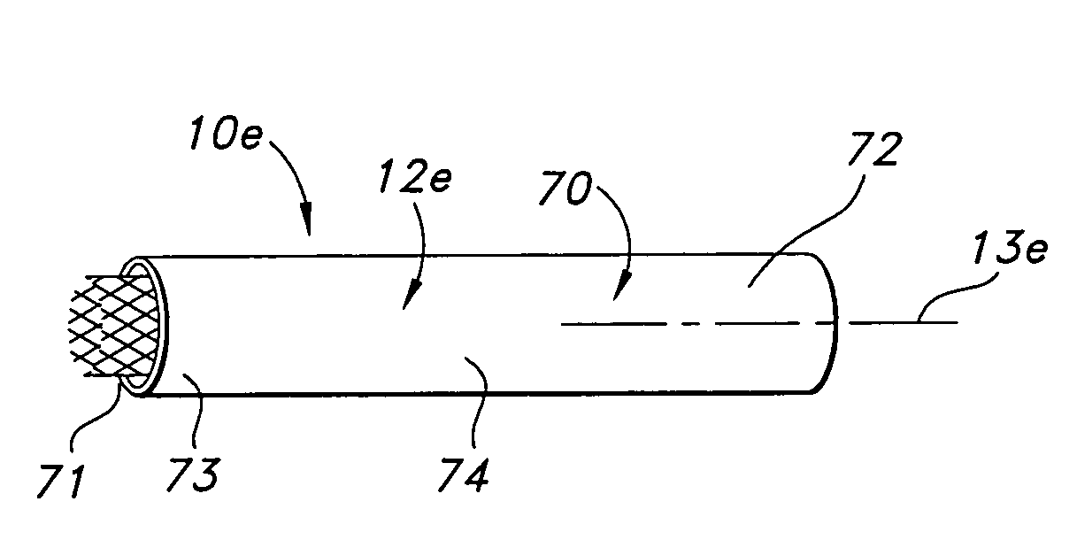
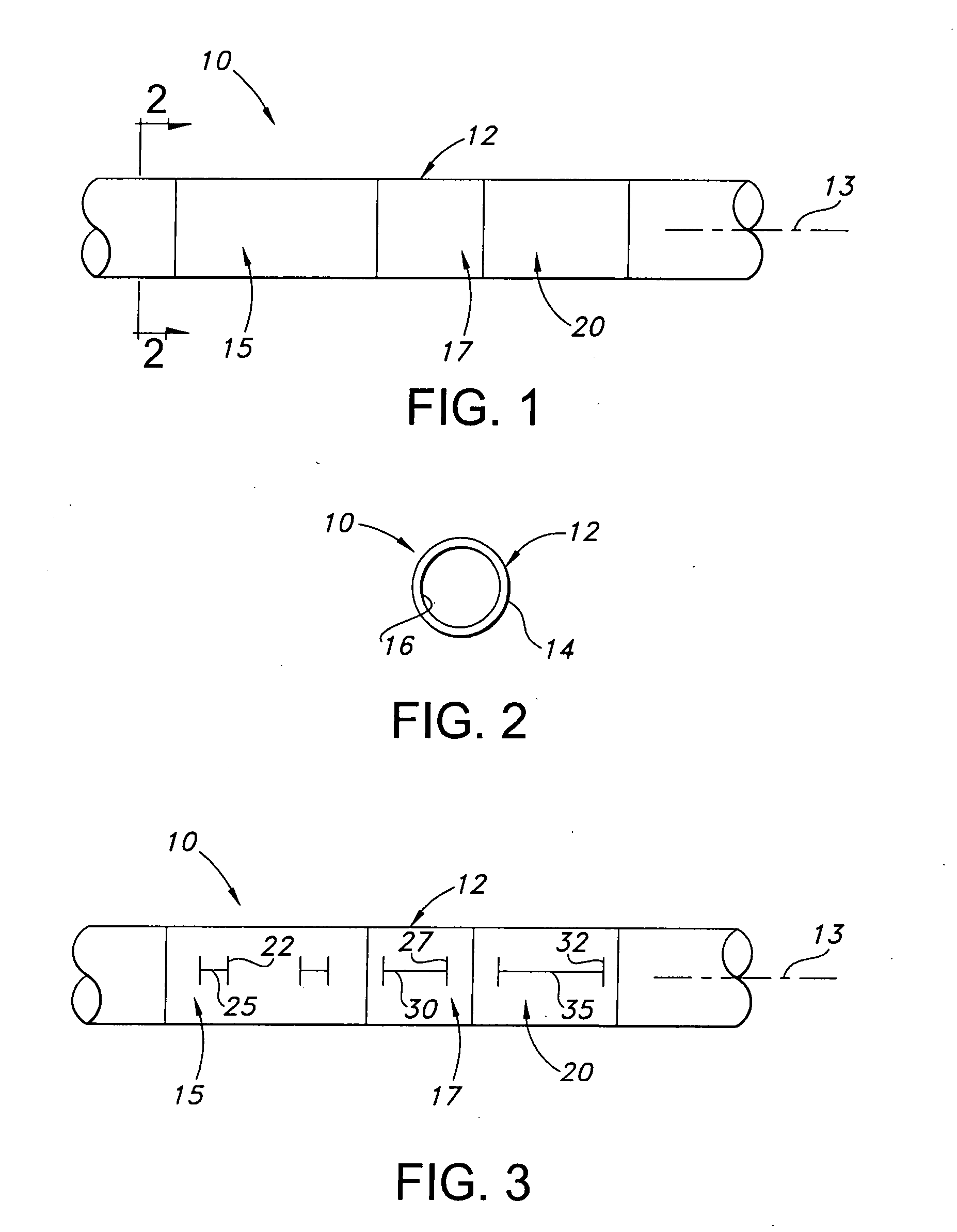
[0034]Referring to the drawings and more particularly to FIGS. 1 and 2, a preferentially varying-density ePTFE structure 10 is shown for implantation within a body. The ePTFE structure 10 shown in FIG. 1 is a tubular structure 12 which has a longitudinal axis 13, and outer and inner surfaces 14, 16. The tubular structure 12 has an annular or ring shaped cross-section, the outer and inner diameters of which are substantially constant along the length of the tubular structure. In alternative embodiments, the ePTFE structure 10 may have non-tubular structures such as a plate or a fiber which has a solid or continuous or closed cross-section. The ePTFE structure 10 is formed of homogeneous material having a fibrous state which is defined by interspaced nodes which are interconnected by elongated fibrils, referred to herein as a “node and fibril microstructure”.

[0035]The tubular structure 12 has longitudinal first, second, and third regions 15, 17, 20. The first, second, and third region...


PUM


Abstract

The ePTFE structure has a node and fibril micro-structure. The ePTFE structure includes first and second regions each of which has a corresponding density. The density of the first region is different from the density of the second region.

Description

FIELD OF THE INVENTION[0001]The present invention relates generally to structures containing expanded polytetrafluoroethylene (ePTFE) and methods for making the same. More specifically, the present invention relates to ePTFE structures having regions of different densities, and methods for making such ePTFE structures.BACKGROUND OF THE INVENTION[0002]It is known to use extruded tube structures of ePTFE as implantable intraluminal prostheses, particularly as grafts for vascular, esophageal, ureteral and enteral applications. ePTFE is particularly suitable as an implantable prosthesis as it exhibits superior biocompatibility. ePTFE tube structures may be used as vascular grafts in the replacement or repair of a blood vessel as ePTFE exhibits low thrombogenicity. In vascular applications, the grafts are manufactured from ePTFE tube structures which have a microporous micro-structure. This micro-structure allows natural tissue ingrowth and cell endothelization once implanted in the vasc...

Claims


Application Information

Patent Timeline
IPC IPC(8): A61F2/06
CPCA61F2/07A61F2/90A61F2250/0023
Inventor DURAN, JULIOHENDERSON, JAMIE S.SOWINSKI, KRZYSZTOF
Owner LIFESHIELD SCI
Why Eureka
Try Eureka