Dirt and dust cyclonic separating apparatus

a cyclonic separation and dust technology, applied in the direction of vortex flow apparatus, filtration separation, separation process, etc., can solve the problem that no prior art arrangement achieves 100% separation efficiency, and achieves high separation efficiency, low efficiency, and high efficiency

Inactive Publication Date: 2010-11-09
DYSON TECH LTD
View PDF30 Cites 23 Cited by
  • Summary
  • Abstract
  • Description
  • Claims
  • Application Information

AI Technical Summary

Benefits of technology

[0008]If the second cyclonic separating unit has a separation efficiency which is the same as the first cyclonic separating unit, this has the effect of providing the incoming airflow with two “sweeps” through a relatively low efficiency cyclone separating unit before the third, higher efficiency, cyclone separating unit is challenged. The airflow is therefore cleaned of larger dirt and dust particles, and also a significant proportion of fine dust, prior to entering the third cyclonic separating unit. The third cyclonic separating unit is thus able to operate under favourable conditions which allow it to achieve a relatively high separation efficiency. In this way, the apparatus as a whole cleans the airflow reliably and to a high standard.
[0009]If the second separating unit has a separation efficiency which is the same as the third cyclonic separating unit, the airflow has two “sweeps” through a relatively high efficiency cyclonic separating unit before it is ejected from the apparatus. Having had any relatively large dirt and debris removed from the airflow, the airflow then makes a first sweep through a relatively high efficiency cyclonic separating unit in which a large proportion of the remaining dust is separated. The third cyclonic separating unit is then allowed to operate under advantageous conditions in which a high separation efficiency can be achieved.
[0010]Preferably, the first cyclonic separating unit comprises a single first cyclone and, more preferably, the or each first cyclone is substantially cylindrical. This arrangement encourages larger particles of dirt and debris to be reliably collected and stored with a relatively low risk of re-entrainment.
[0011]Preferably, the second cyclonic separating unit comprises a plurality of second cyclones arranged in parallel and the third cyclonic separating unit comprises a plurality of third cyclones arranged in parallel and, more preferably, the number of second cyclones is lower than the number of third cyclones. The increasing number of cyclones in each successive cyclonic separating unit allows the size of each individual cyclone to decrease in the direction of the airflow. The fact that the airflow has passed through a number of upstream cyclones means that the larger particles of dirt and dust will have been removed which allows each smaller cyclone to operate efficiently and without risk of blockage.

Problems solved by technology

None of the prior art arrangements achieves 100% separation efficiency (ie the ability reliably to separate entrained dirt and dust from the airflow), particularly in the context of use in a vacuum cleaner.

Method used


Image

  • Dirt and dust cyclonic separating apparatus
  • Dirt and dust cyclonic separating apparatus
  • Dirt and dust cyclonic separating apparatus

Examples


Embodiment Construction

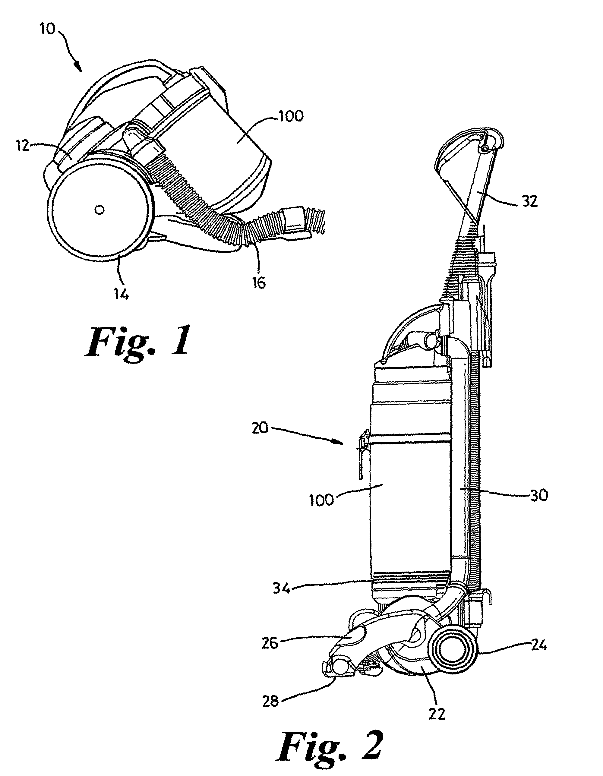
[0020]FIG. 1 shows a cylinder vacuum cleaner 10 having a main body 12, wheels 14 mounted on the main body 12 for manoeuvring the vacuum cleaner 10 across a surface to be cleaned, and cyclonic separating apparatus 100 also mounted on the main body 12. A hose 16 communicates with the cyclonic separating apparatus 100 and a motor and fan unit (not shown) housed within the main body 12 for drawing a dirty airflow into the cyclonic separating apparatus 100 via the hose 16. Commonly, a floor-engaging cleaner head (not shown) is coupled to the distal end of the hose 16 via a wand to facilitate manipulation of the dirty air inlet over the surface to be cleaned.

[0021]In use, air drawn into the cyclonic separating apparatus 100 via the hose 16 has entrained dirt and dust separated therefrom in the cyclonic separating apparatus 100. The dirt and dust is collected within the cyclonic separating apparatus 100 while the cleaned air is channeled past the motor for cooling purposes before being eje...


PUM

PropertyMeasurementUnit
shapeaaaaaaaaaa
angle of taperaaaaaaaaaa
angleaaaaaaaaaa

Abstract

A cyclonic separating apparatus includes a first cyclonic separating unit including at least one first cyclone, a second cyclonic separating unit located downstream of the first cyclonic separating unit and including at least one second cyclone, and a third cyclonic separating unit located downstream of the second cyclonic separating unit and including at least one third cyclone. The separation efficiency of the second cyclonic separating unit is substantially the same as the separation efficiency of either the first cyclonic separating unit or the third separating unit, providing an apparatus which achieves a higher separation efficiency than known separation apparatus.

Description

REFERENCE TO RELATED APPLICATIONS[0001]This application is a national stage application under 35 USC 371 of International Application No. PCT / GB2006 / 001678, filed May 9, 2006, which claims the priority of United Kingdom Application No. 0510862.6, filed May 27, 2005, the contents of both of which prior applications are incorporated herein by reference.FIELD OF THE INVENTION[0002]The invention relates to cyclonic separating apparatus. Particularly, but not exclusively, the invention relates to cyclonic separating apparatus suitable for use in vacuum cleaners.BACKGROUND OF THE INVENTION[0003]Vacuum cleaners which utilise cyclonic separating apparatus are well known. Examples of such vacuum cleaners are shown in EP 0042723, U.S. Pat. Nos. 4,373,228, 3,425,192, 6,607,572 and EP 1268076. In each of these arrangements, first and second cyclonic separating units are provided with the incoming air passing sequentially through each separating unit. In some cases, the second cyclonic separatin...

Claims


Application Information

Patent Timeline
Patent Type & Authority Patents(United States)
IPC IPC(8): B01D45/12A47L9/16B01D45/16B04C5/26B04C5/28
CPCA47L9/1625A47L9/1641B01D45/16B04C5/26B04C5/28Y10S55/03A47L9/16
Inventor COURTNEY, STEPHEN BENJAMINDYSON, JAMESGOMICIAGA-PEREDA, RICARDO
Owner DYSON TECH LTD
Why Eureka
Try Eureka