Production of nanosized materials

a nano-sized material and nano-sized technology, applied in the field of nano-sized materials, can solve the problems of time-consuming, needing after treatment, and specific surface area may be reduced by up to 80%, and achieve the effects of small average diameter, controlled particle morphology, and high purity

Inactive Publication Date: 2010-11-09
SCF TECH AS
View PDF12 Cites 16 Cited by
  • Summary
  • Abstract
  • Description
  • Claims
  • Application Information

AI Technical Summary

Benefits of technology

[0025]An objective of present invention may be to address the quality and availability of nano-sized materials by providing a method for production of such materials, which allows production of more homogeneous nano-materials than in the until now known methods i.e. nano-materials with a high purity and / or a controlled particle morphology, and / or a small average diameter and / or a narrower size distribution, and / or a more controlled phase and / or structure.
[0042]By this way of controlling the zeta potential and / or the pH value a stable suspension may be provided and the risk of precipitation and depositing of the produced nano material may become very limited whereby blocking by depositing of produced nano materials in the flow passages may be avoided.

Problems solved by technology

The key drawbacks from the sol-gel process are that it is time consuming, and need after treatment such as drying and calcinations.
In addition to a higher energy usage and a more complicated process this has the unfortunate effect that substantially growth of primary particles occurs, and that the specific surface area may be decreased by up to 80%.
A major drawback is the relatively long reaction and aging time e.g. hours to days required at low to medium temperatures and the very corrosive environment at higher temperature.
Typical the result is a product having a wide particle size distribution, and it is difficult to obtain a uniform product with well defined characteristics in the nanoregime.
However, though it do not disclose information of important characteristics such as primary particle size and secondary particle size, particle size distribution / -s, and how such characteristics is controlled.
Although the known methods and devices may have the potential to produce nano sized material, they still suffer from being able to efficiently producing a uniformly sized nano material and the devices used for producing the materials are typically blocked by the material being formed.
Thereby a thermal boundary layer is generated inside the reactor where for instancethe temperature of the fluid close to the wall of the reactor is so high that the reactants are destroyed,the temperature of the fluid in the center of the reactor is so low that unwanted reactions takes place.
In addition to this, the time needed for heating the fluid is typically so long that, again, unwanted reactions take place.
Such locally formation of nano materials close to a surface results often in depositing of nano materials on the surface—in particular as the nano material formed precipitates from the fluid—resulting in blockage of the mixing device.
Although great effect may be put into the design of heat exchangers to minimize the thermal boundary layer precipitation and deposition on surfaces may still occur which tends to block the flow passages.
Thus, while many of the processes and devices suggested earlier have shown to be able to produce nano sized materials in short production runs and at laboratory scale, they still seem to suffer from not being scalable to longer production runs and with a higher output.

Method used


Image

  • Production of nanosized materials
  • Production of nanosized materials
  • Production of nanosized materials

Examples


example 1

ILLUSTRATIVE EXAMPLE 1

Production of TiO2 with a Mixture of Crystal Phases

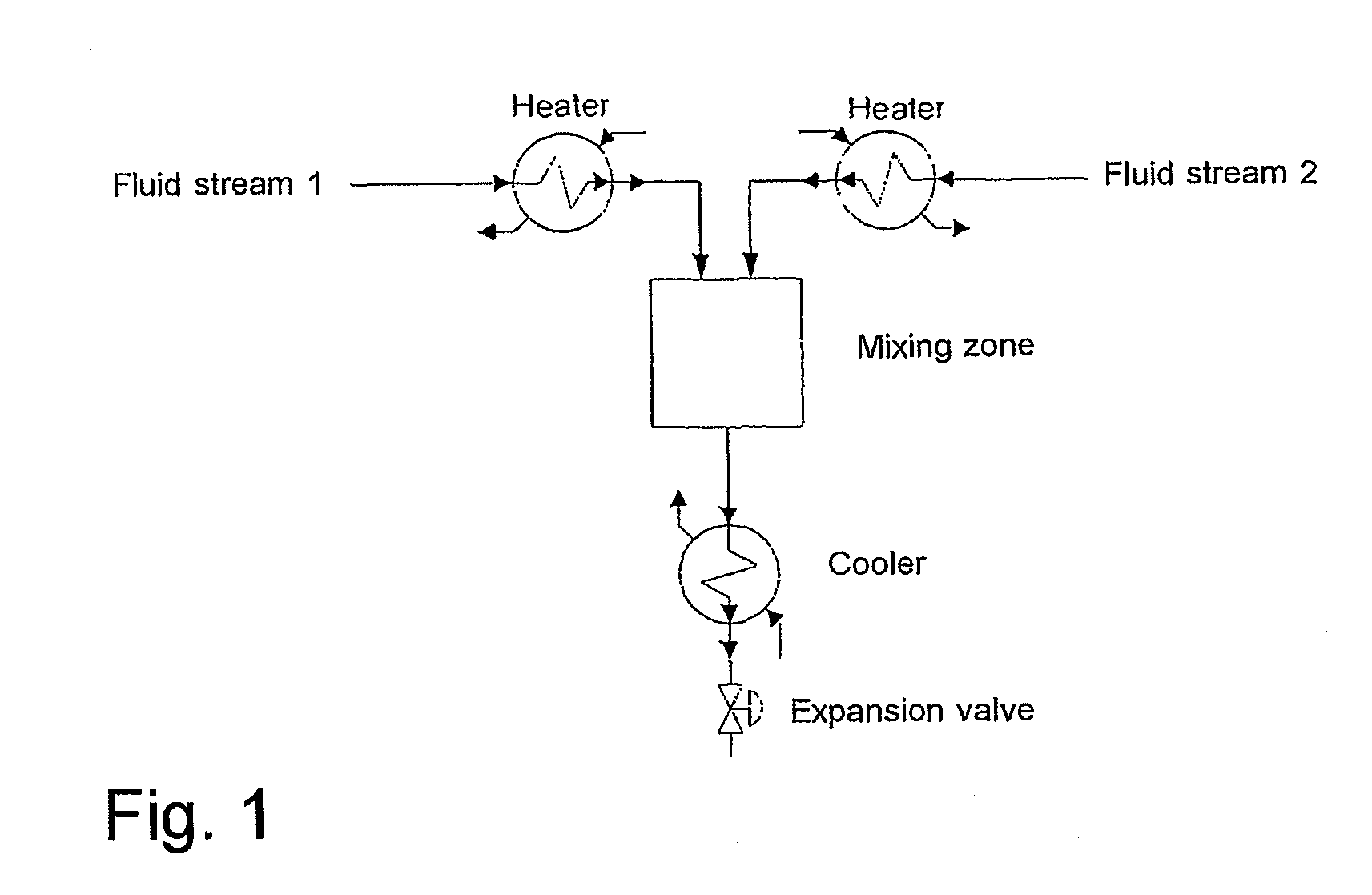
[0107]Nano sized materials comprising mixed crystal phases are important for many practical applications. According to an aspect of the present invention such mixed crystal phases may be produced from a precursor mixture comprising two or more metal alkoxides, metal nitrides, metal sulphates or metal salts, so as to obtain different crystal phases in the same metal oxide product. Different crystal phases may be synthesized from certain metal precursors. For example using a mixture of titanium isopropoxide and amino titanium oxalate leads to a mixture of anatase and rutile, whereas, amino titanium oxalate may used for synthesizing rutile at low temperatures.

example 2

ILLUSTRATIVE EXAMPLE 2

Stabilized and or Doped Metal Oxides

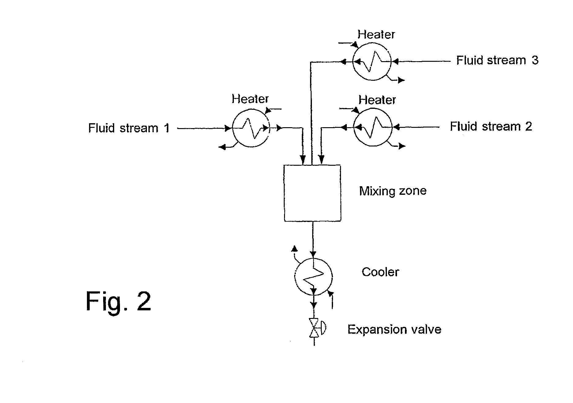
[0108]Doped metal oxides and / or stabilized metal oxides are important for many technical applications, e.g. photocatalysis or solid oxide fuel cells. Such doped or stabilized metal oxides may according to the present invention be produced by introducing precursors for said doping metal in fluid 2 or in a separate reactant stream, Reactant stream 3.

example 3

ILLUSTRATIVE EXAMPLE 3

PZT Coating—Three Steps Mixing

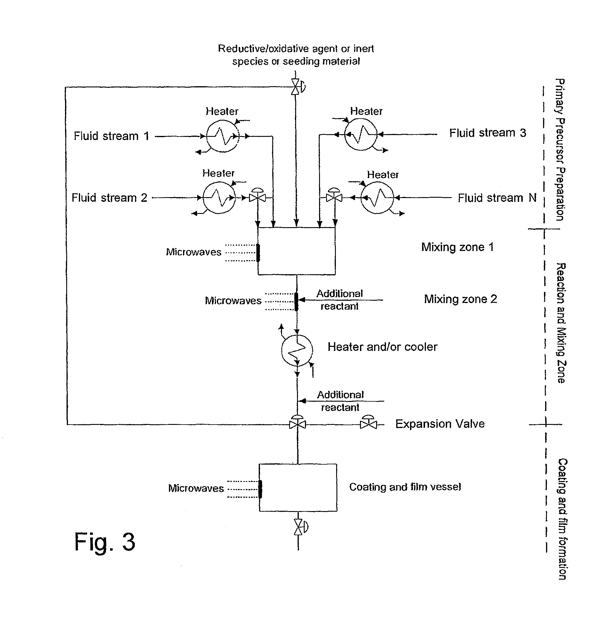
[0109]PZT (Pb(ZrxTi1-x)O3) coatings may be produced according to the present invention through a three steps mixing process as shown in FIG. 4. Reactant stream 1 may be a titania precursor for example titanium isopropoxide preheated before entering the mixing point 1. Reactant stream 2 may be a zirconia precursor for example zirconium n-propoxide preheated before entering mixing point. Reactant stream 1 and reactant stream 2 may according to another aspect of the present invention also be mixed prior to entering mixing point 1. One or more chelating ligands or / and stabilizing agents or / and catalysts may also be introduced in mixing point 1 to stabilize the sol / -s. Reactant stream 3 could be a lead precursor such as lead acetate preheated before entering mixing point 2. Reactant stream 1-3 may comprise the same solvent or one or more streams may comprise / -s a different solvent / -s. After mixing point two a stable sol may be created a...


PUM

PropertyMeasurementUnit
temperatureaaaaaaaaaa
zeta potentialaaaaaaaaaa
pressureaaaaaaaaaa

Abstract

The present invention relates to a method of producing a nano-sized material such as in the form of a colloidal suspension of nano-sized particles and / or as a coating and / or as a thin film comprised by such nano-sized particles on the surface of a substrate. The invention also relates to an apparatus for carrying out the method according to the present invention.

Description

CROSS REFERENCE TO RELATED APPLICATION[0001]This application is a national phase application of and claims the benefit of priority to PCT / DK / 2006 / 000706, filed Dec. 11, 2006, which designated the United States and was published in English and claims the benefit of priority to Danish Patent Application No. 2005 01755, filed on Dec. 11, 2005. The disclosures of all of the aforementioned applications are hereby expressly incorporated by reference in their entirety.[0002]The present invention relates to a method of producing a nano-sized material such as in the form of a colloidal suspension of nano-sized particles and / or as a coating and / or as a thin film comprised by such nano-sized particles on the surface of a substrate. The invention also relates to an apparatus for carrying out the method according to the present invention.BACKGROUND[0003]There is an increasing interest in nano-sized materials in numerous technical applications. Such nano-structured materials are cornerstones in m...

Claims


Application Information

Patent Timeline
Patent Type & Authority Patents(United States)
IPC IPC(8): B01F3/12C09K23/00
CPCB01J13/00B82Y30/00C01G1/02C01G23/053C01G25/006C01G25/02C23C18/02C23C18/1216C23C18/1254C23C18/1266C23C18/1283C23C18/14C01P2004/64C23C18/143C01G23/047B01J13/02
Inventor IVERSEN, STEEN BRUMMERSTEDTJENSEN, HENRIK
Owner SCF TECH AS
Why Eureka
Try Eureka