Coupling cancellation scheme

a cancellation scheme and coupling technology, applied in the field of electronic devices, can solve problems such as adversely affecting the accuracy of information transmitted over the lin

Active Publication Date: 2010-11-09
MICRON TECH INC
View PDF18 Cites 17 Cited by
  • Summary
  • Abstract
  • Description
  • Claims
  • Application Information

AI Technical Summary

Problems solved by technology

This electrical coupling adversely affects the accuracy of information transmitted over the lines.

Method used


Image

  • Coupling cancellation scheme
  • Coupling cancellation scheme
  • Coupling cancellation scheme

Examples


Embodiment Construction

[0021]The concepts and principles of the embodiments described below are presented herein in the context of an integrated circuit. A skilled artisan will, however, appreciate that the concepts and principles of the embodiments are applicable to other circuits, including, but not limited to, printed circuit (PC) boards, such as a board for a DIMM module or a memory module.

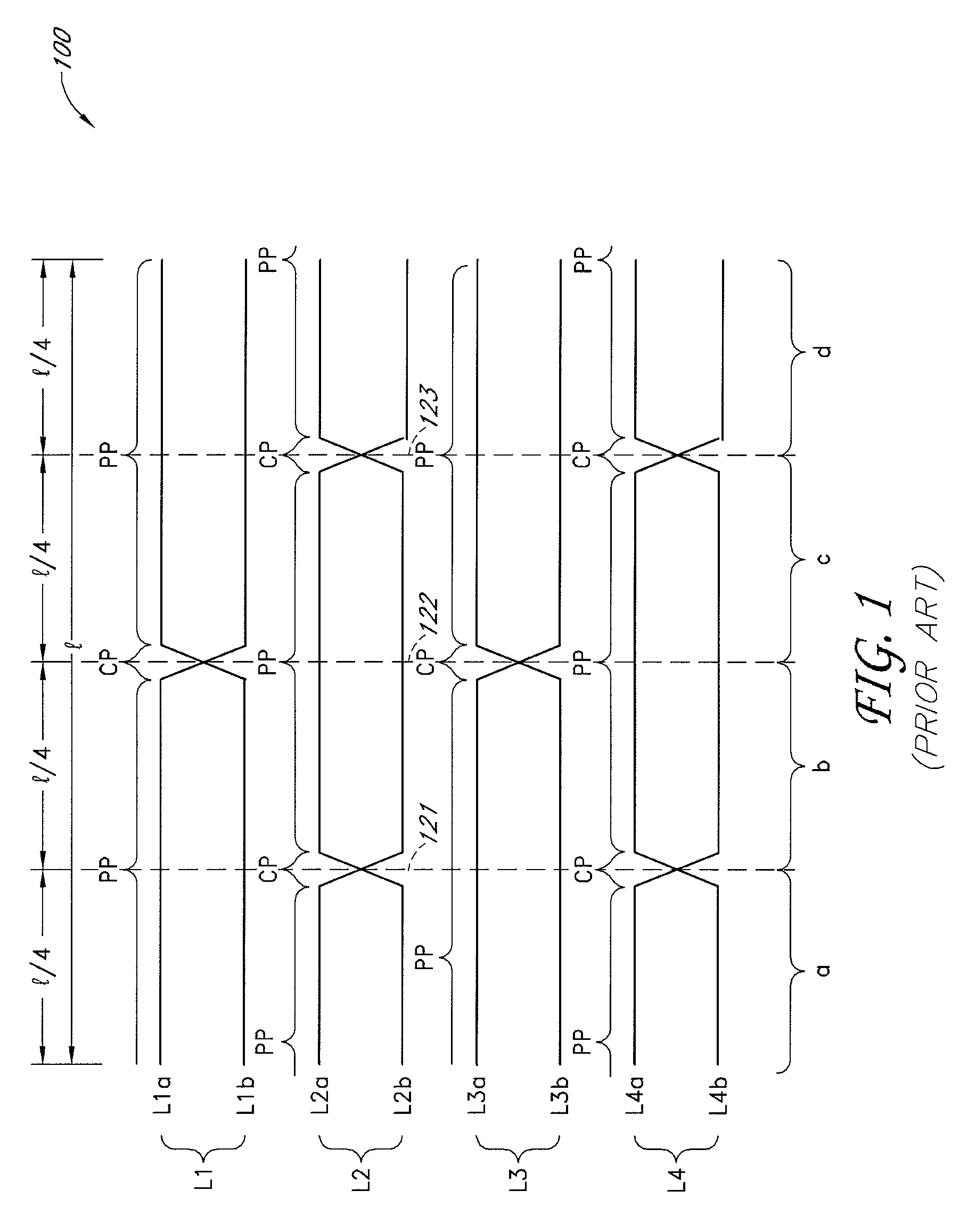
[0022]The layout 100 described above with reference to FIG. 1 cancels inter-pair coupling among separate differential pairs. However, the layout 100 does not cancel or reduce intra-pair coupling within a differential pair. Since signals of a differential pair are opposite in polarity to each other, intra-pair coupling can attenuate the signal levels. Thus, there is a need to provide a scheme that can reduce or eliminate intra-pair coupling as well as inter-pair coupling.

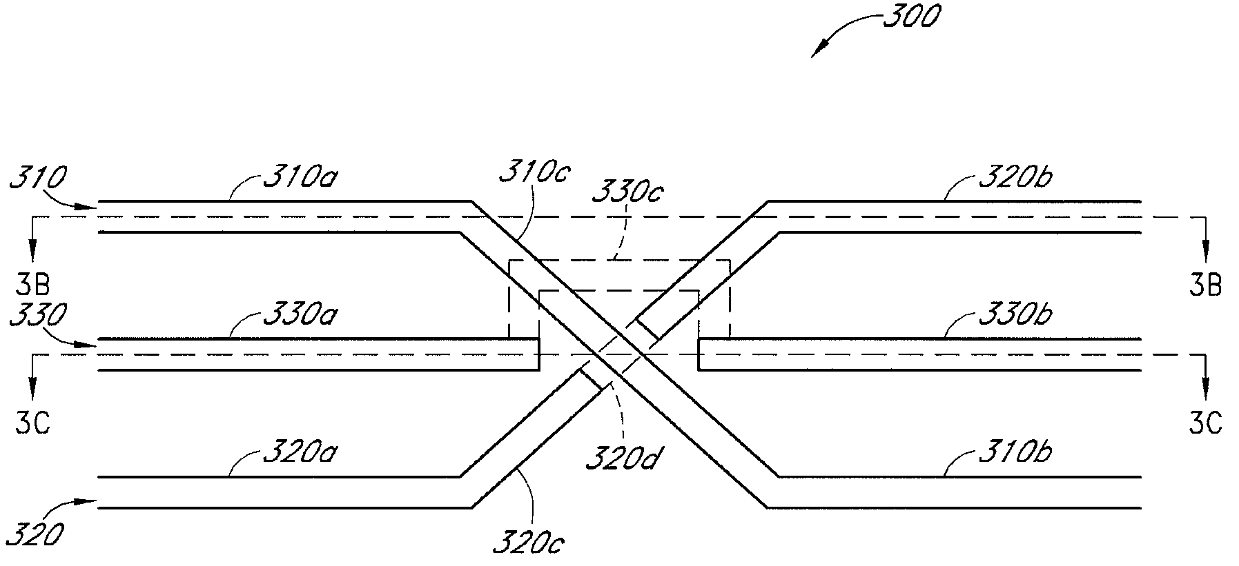
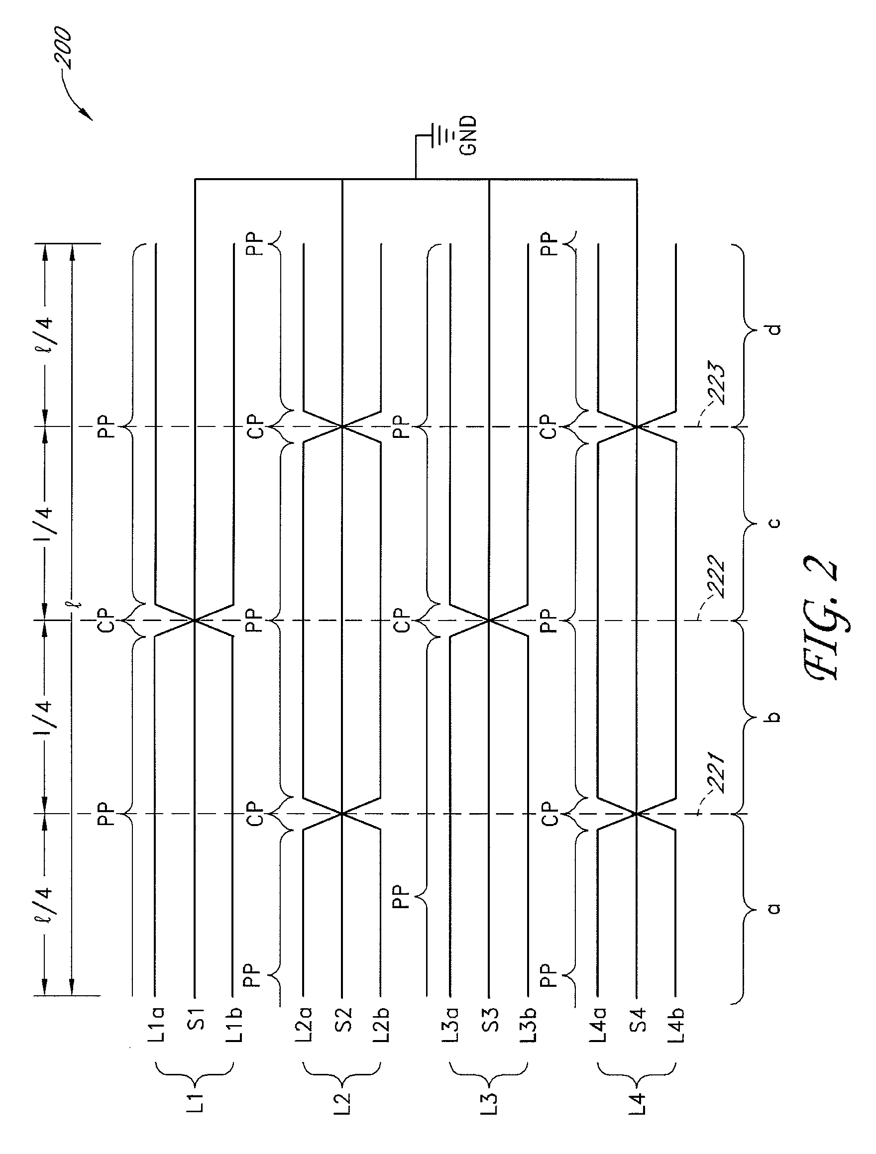
[0023]In one embodiment, an interconnection layout for differential signaling can have differential pairs similar to those described with reference ...


PUM


Abstract

Methods and apparatus are disclosed, such as those involving an interconnection layout for an integrated circuit (IC). One such layout includes a plurality of differential pairs of lines. Each differential pair has two lines including one or more parallel portions extending substantially parallel to each other. Each pair also includes a shield line. Each of the shield lines includes one or more parallel portions interposed between the parallel portions of one of the pairs of differential lines. One or more of the shield lines are electrically connected to a voltage reference, such as ground. This layout is believed to reduce or eliminate intra-pair coupling as well as inter-pair coupling.

Description

BACKGROUND OF THE INVENTION[0001]1. Field of the Invention[0002]Embodiments of the invention relate to electronic devices, and more particularly, in one or more embodiments, to an interconnection layout for integrated circuits and / or printed circuit boards.[0003]2. Description of the Related Art[0004]In many applications in which electronic information is transmitted over a relatively long line, differential signaling has been widely used. Differential signaling is a method of transmitting information using two complementary signals sent on two separate lines. A differential circuit at a receiving end detects and compares the complementary signals, and determines logic changes based on the changes of one of the signals with reference to the other. Differential signaling is known to provide a relatively fast and accurate data transmission mechanism.[0005]In differential signaling, however, a pair of lines carrying complementary signals can have electrical coupling or cross-talk betwe...

Claims


Application Information

Patent Timeline
Patent Type & Authority Patents(United States)
IPC IPC(8): H01P3/02
CPCH01P3/026H01P3/081
Inventor MERRITT, TODD
Owner MICRON TECH INC
Why Eureka
Try Eureka