Mixer arrangement, use of the mixer arrangement and method for frequency conversion

a technology of mixer arrangement and mixer, which is applied in the direction of dc-amplifiers with dc-coupled stages, dc-amplifiers with semiconductor devices/discharge tubes, and transceivers. it can solve the problems of reducing the changeover speed, affecting the overall performance, and increasing the load of the driver circuit, so as to reduce the common-mode current, maintain linearity performance, and reduce flicker noise

Inactive Publication Date: 2010-11-09
INTEL CORP
View PDF22 Cites 13 Cited by
  • Summary
  • Abstract
  • Description
  • Claims
  • Application Information

AI Technical Summary

Benefits of technology

[0012]The present invention includes a mixer arrangement which makes it possible to reduce the common-mode current through the actual mixer cell as far as a completely currentless switching of the mixer cell. The further reduction of the current leads to a reduction of flicker noise whilst at the same time maintaining the linearity performance. In addition, it is also possible in this way to dispense with a complicated fluorine implantation of the transistors.

Problems solved by technology

However, this leads to an increased loading on the driver circuits for providing the local oscillator signal and thus to a reduction of the changeover speed.
Since flicker noise principally becomes apparent at the changeover instant at the output of the frequency converter, the overall performance may be impaired as a result.
This decreases the direct current through the mixer cell 1 and thus the flicker noise as well.
This technology option relates primarily to production, where it causes additional process steps and hence an increase in the production costs.

Method used


Image

  • Mixer arrangement, use of the mixer arrangement and method for frequency conversion
  • Mixer arrangement, use of the mixer arrangement and method for frequency conversion
  • Mixer arrangement, use of the mixer arrangement and method for frequency conversion

Examples


Embodiment Construction

[0023]The embodiments illustrated below are in no way restrictive. They can be combined or modified as desired without contravening the essence of the invention. The configurations set forth thus form possible and in no way finally enumerated embodiments of the invention.

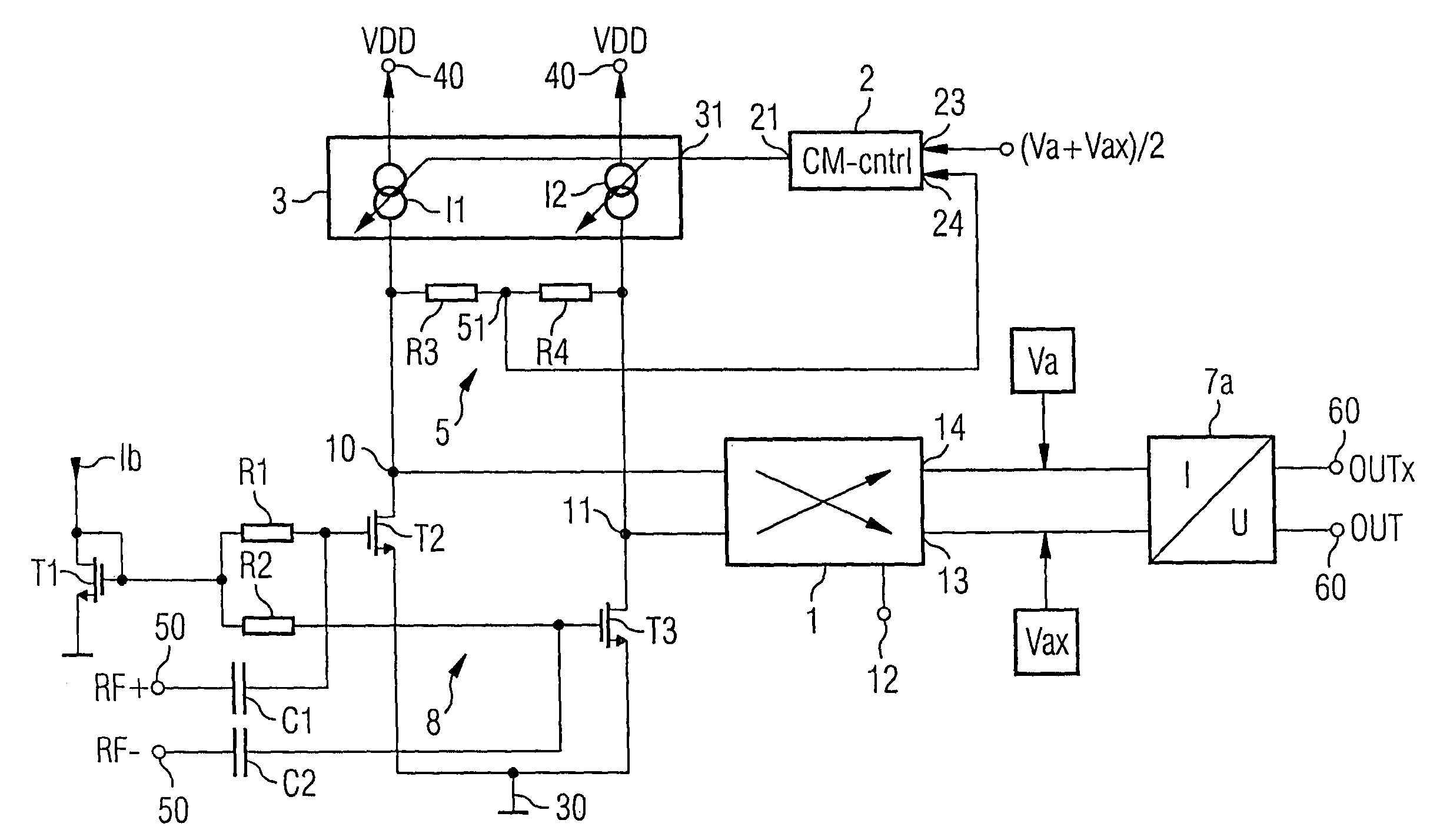
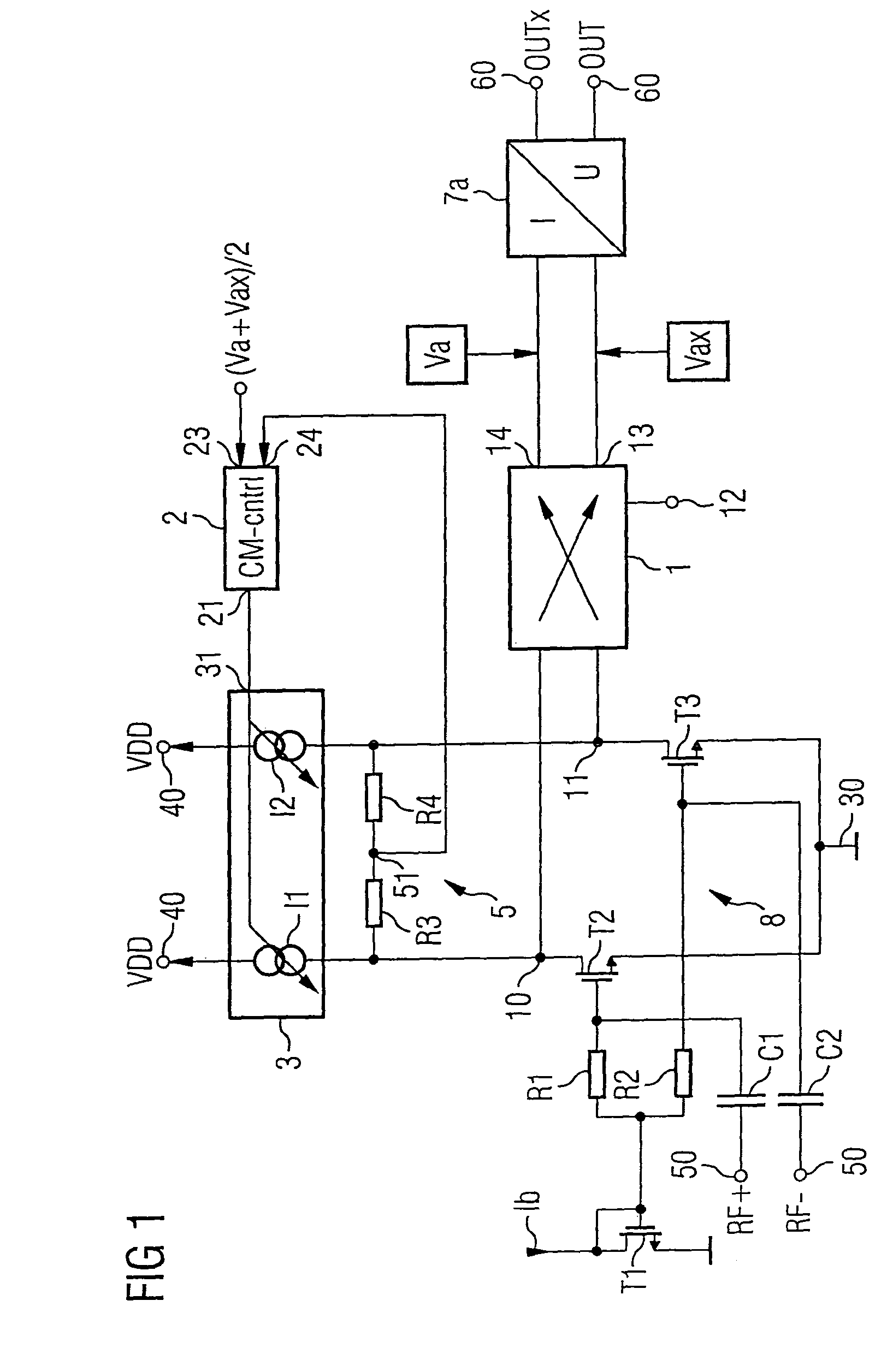
[0024]In one possible embodiment, a mixer arrangement in accordance with the principle proposed may comprise, for example, a mixer input for feeding in a radiofrequency signal. A mixer cell is coupled by a signal input to the mixer input. The mixer cell has a local oscillator input and a signal output. The mixer cells converts a signal on the input side to an intermediate frequency with the aid of a signal at the local oscillator input. A first current source is coupled to the signal input of the mixer cell. A second current source is likewise connected to the signal output of the mixer cell. At least one of the first and of the second current source comprises a regulatable current source having a control input. Fur...


PUM


Abstract

A mixer arrangement includes a mixer cell coupled by a signal input to a mixer input, and is embodied for frequency conversion of a signal present on the input side to an intermediate frequency. A first current source is coupled to the signal input of the mixer cell, and a second current source is coupled to a signal output of the mixer cell. The mixer arrangement furthermore includes a sensor circuit embodied for detection and for outputting of a value which is derived from a current of one of the current sources. A desired value regulating circuit is coupled by a feedback input to the sensor circuit and is designed for outputting a regulating signal to the one current source derived from a comparison of a signal present at a feedback input with a desired value.

Description

REFERENCE TO RELATED APPLICATIONS[0001]This application claims the benefit of the priority date of German application DE 10 2005 028 747.6, filed on Jun. 21, 2005, the contents of which are herein incorporated by reference in their entirety.FIELD OF THE INVENTION[0002]The invention relates to a mixer arrangement and a use of the mixer arrangement. The invention furthermore relates to a method for frequency conversion.BACKGROUND OF THE INVENTION[0003]Frequency mixers, generally also called frequency converters, form important components in a multiplicity of different applications pertaining to radiofrequency technology. They generally serve to convert a signal having a first center frequency to an output signal having a second frequency with the aid of a local oscillator signal. In this case a distinction is made between mixers in which the frequency of the output signal is greater than the frequency of the input signal and mixers in which the frequency of the output signal is less t...

Claims


Application Information

Patent Timeline
Patent Type & Authority Patents(United States)
IPC IPC(8): H04B1/26
CPCH03D7/1441H03D7/1433H03D7/1458H03D7/1466H03D7/165H03D2200/0019H03D2200/0043H03D2200/0033H03D2200/0084
Inventor SCHELMBAUER, WERNERZIPPER, JOSEF
Owner INTEL CORP
Why Eureka
Try Eureka