Mixing apparatus and container for such

a technology of mixing apparatus and container, which is applied in the direction of mixers, bearings, biochemistry apparatus, etc., can solve the problems of contaminated containers, difficult to ensure homogeneous and gradient-free mixing of different components, and sterility at risk, so as to achieve more homogeneous or faster mixing, and the effect of simple apparatus

Active Publication Date: 2010-11-16
LEVITRONIX
View PDF15 Cites 37 Cited by
  • Summary
  • Abstract
  • Description
  • Claims
  • Application Information

AI Technical Summary

Benefits of technology

[0013]Another preferred embodiment is that the drive unit includes a stator which, together with the mixing member as the rotor, forms an electrical rotary drive. In this embodiment, the mixing element is therefore itself part of the electrical rotary drive, namely its rotor. The mixing member is particularly preferably designed as a permanently magnetic rotor which, together with the stator, forms a bearing-free motor in which the stator is designed as a bearing and drive stator for the permanently magnetic rotor. This embodiment as a bearing-free motor is extremely compact and space-saving because no separate magnetic bearings are needed for the rotor, but rather the stator both generates the drive torque for the rotor and realizes the magnetic journaling of the rotor.
[0014]An embodiment has a particularly simple apparatus when the drive unit is arranged suspended in the cut-out. The drive unit can then be moved up and down in the cut-out in a simple manner via a cable winch or a chain in order thus to vary the position of the mixing member in the container in a controlled manner.
[0015]It is an advantageous measure that the inwardly disposed end of the cut-out has a beaker-like reinforcement, in particular made from plastic. This reinforcement serves as a support surface for the mixing member when the drive unit is deactivated. The reinforcement prevents damage to the wall of the cut-out.
[0016]An advantageous variant is that the drive unit is movable transversely to the longitudinal direction of the central cut-out. The mixing member can not only be moved in the longitudinal direction of the cut-out by this measure, but also in a plane perpendicular thereto. This is in particular advantageous with larger containers to achieve a more homogeneous or faster mixing.

Problems solved by technology

Such processes have therefore usually been carried out in stainless steel tanks, glass tanks or chromium tanks which have previously been sterilized in a complex and / or expensive manner.
Since the processes are frequently carried out under a controlled atmosphere, that is, in vessels which are closed with respect to the environment, the lead-through of the rotating axles into the vessel represents a possible source of contamination, for example also due to abrasion in the slide seal rings of the shaft.
Furthermore, microorganisms can collect in the lead-throughs which put the sterility at risk, for example.
It is also frequently very difficult to ensure a homogeneous and gradient-free mixing of the different components when using agitators or mixers.

Method used


Image

  • Mixing apparatus and container for such
  • Mixing apparatus and container for such
  • Mixing apparatus and container for such

Examples


first embodiment

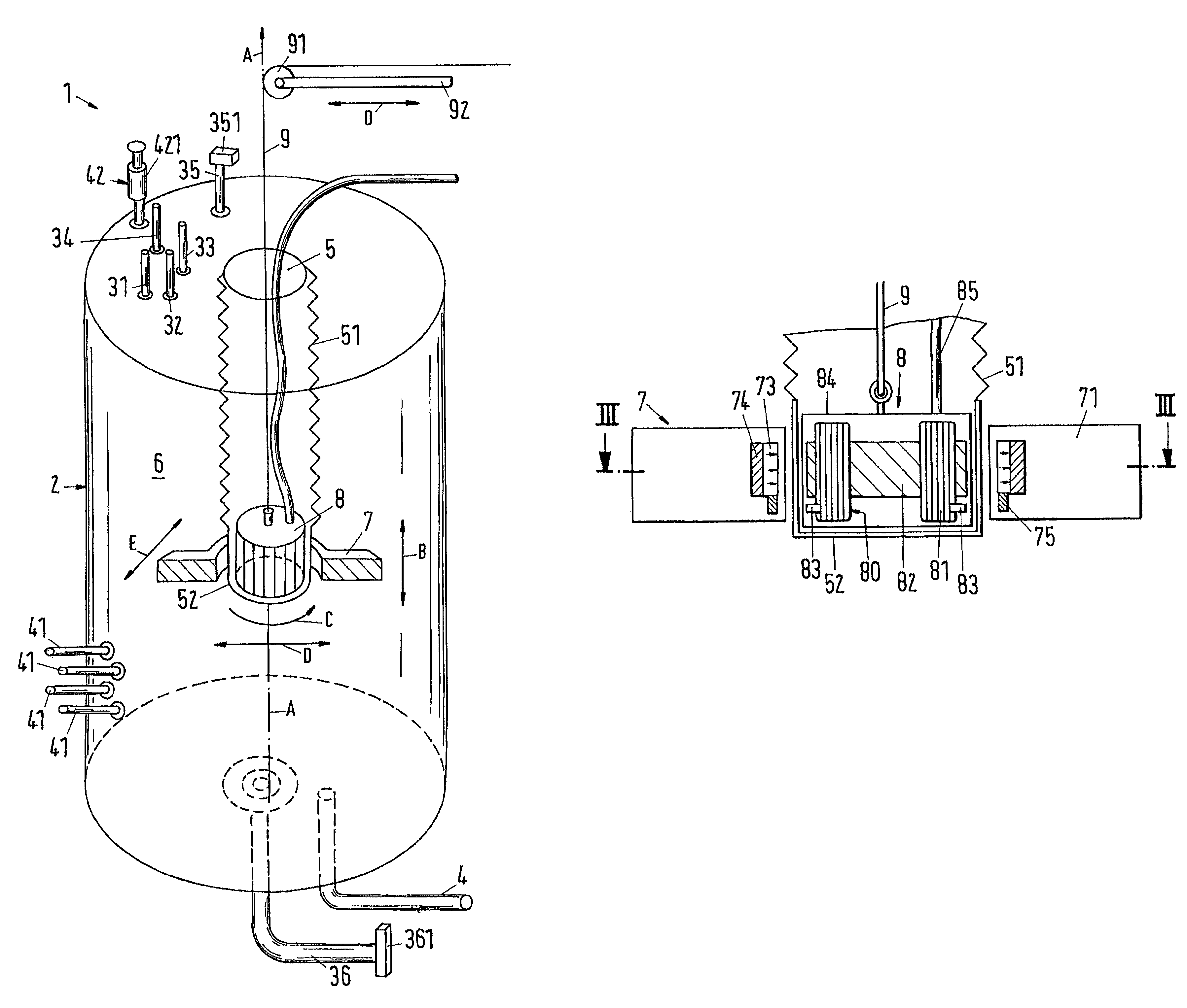
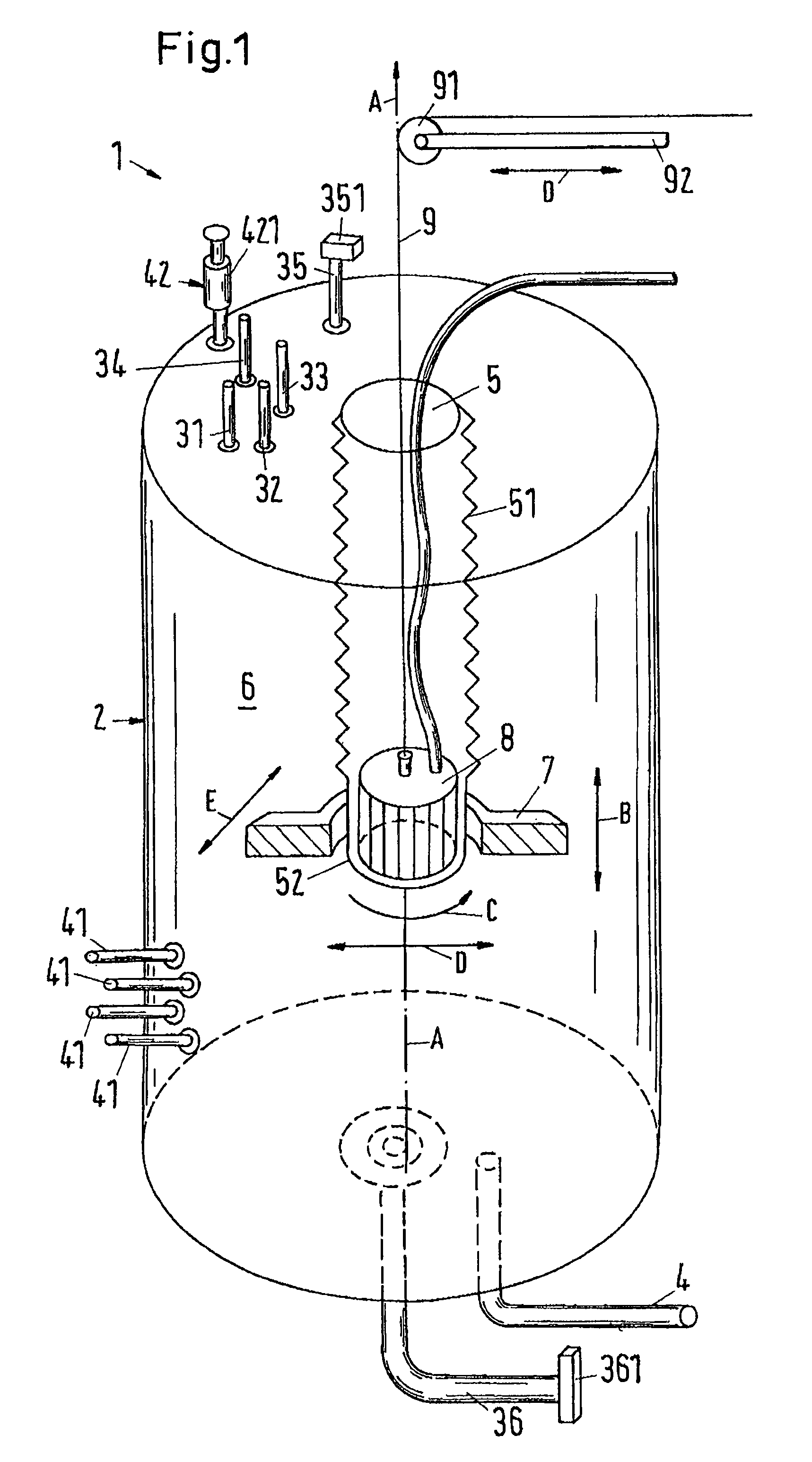
[0035]FIG. 1 shows, in a schematic, partly sectioned representation, a mixing apparatus in accordance with the invention which is designated as a whole by the reference numeral 1. In the following description of the invention, reference is made with exemplary character to the case which is important for practice that the mixing apparatus in accordance with the invention is designed as a bioreactor or as a fermenter. It is, however, understood that the invention is not limited to such embodiments but rather relates very generally to mixing apparatus with which media are mixed. These media can in particular be fluids or solids, preferably powder. The mixing apparatus in accordance with the invention is suitable for the mixing of liquids among one another and / or for the mixing of at least one liquid with a powder or another solid and / or for the mixing of gases with liquids and / or solids.

[0036]The first embodiment shown in FIG. 1 shows a mixing apparatus 1 which is designed as a bioreac...

third embodiment

[0094]This third embodiment enables an optimum utilization of flexible containers 2 such as plastic sacks. After respective use, the container 2 can be disposed of and can be replaced by a new disposable container 2. Complex and / or expensive sterilization work is thereby omitted.

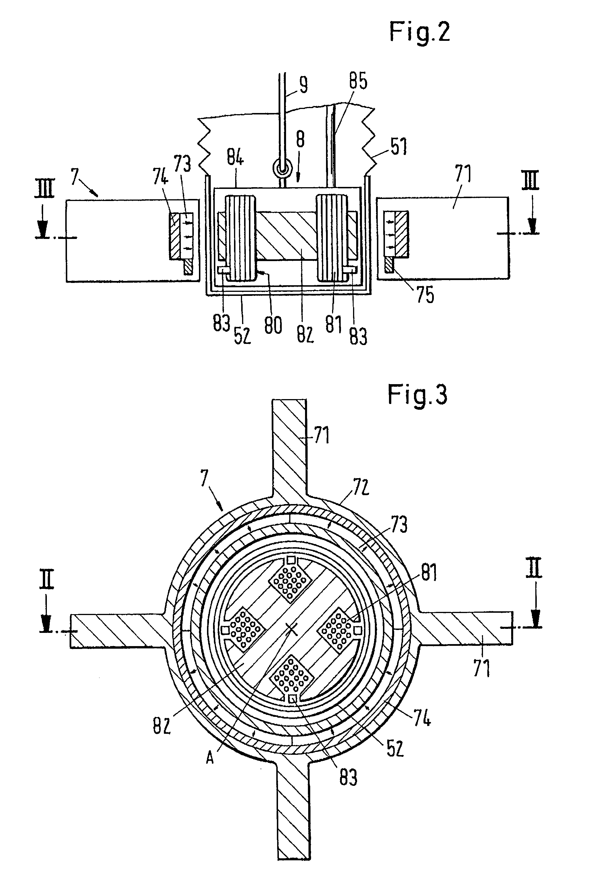
[0095]Furthermore, a container 2 for a mixing apparatus is proposed by the invention which is in particular suitable for a mixing apparatus in accordance with the invention. The container 2 is designed as a flexible bag for single use only and includes a permanently magnetic mixing member 7 which can be designed as in the embodiments described above. The container 2 has a central cut-out 5 in which a drive unit 8 can be movably arranged, with this movement being possible over a substantial portion and preferably over the total extent of the container 2 in the direction of the cut-out 5. The cut-out 5 is preferably bounded by a wall 51 which is flexible and is designed such that the extent of the cut-out 5 is...


PUM


Abstract

A mixing apparatus is proposed having a container (2) for the mixing of media which has at least one inlet (31, 32, 33, 34, 35, 36) for the media to be mixed or at least one outlet (4), with a central cut-out (5) being provided which extends in a longitudinal direction (A) into the container and is bounded relative to the inner space (6) of the container (2) by a wall (51), with a permanently magnetic mixing member (7) being provided in the container (2) adjacent to the cut-out (5) for the mixing of the media, and with a drive unit (8) being provided in the cut-out (5) by which the mixing member (7) can be set into rotation via a magnetic coupling. The drive unit (8) is movably arranged in the cut-out (5) such that the position of the mixing member (7) in the container is variable in a controlled manner.

Description

[0001]This application claims the priority of European Application No. 07122018.0, filed on Nov. 30, 2007, the disclosure of which is incorporated herein by reference.BACKGROUND OF THE INVENTION[0002]The invention relates to a mixing apparatus having a container for the mixing of media as well as to a container for such a mixing apparatus.[0003]Solutions and suspensions are frequently produced in the pharmaceutical industry and in the biotechnological industry which require a careful mixing of the components. Examples for this are the deactivation of viruses by a huge change in the pH or the production of buffers. Processes in bioreactors in which especially grown microorganisms or cells are cultivated in a culture medium under conditions which are as ideal as possible to obtain either the cells themselves, e.g. tissue cells, or parts thereof or their metabolic products, also frequently require a careful mixing of the cell cultures with gases.[0004]All these processes share the feat...

Claims


Application Information

Patent Timeline
Patent Type & Authority Patents(United States)
IPC IPC(8): B01F13/08
CPCB01F7/00716B01F7/00925B01F7/0095B01F13/0827B01F15/00071B01F15/00831B01F15/0085C12M23/14C12M27/02F16C32/0493B01F2215/0032B01F2215/0073F16C2380/26B01F27/2124B01F27/23B01F27/2312B01F33/453B01F35/146B01F35/51B01F35/513B01F2101/22B01F2101/44
Inventor SCHOEB, RETO
Owner LEVITRONIX
Why Eureka
Try Eureka