Card connector

a card connector and card connector technology, applied in the direction of coupling device connection, instruments, conveying record carriers, etc., can solve the problems of unsatisfactory convenience of use, damage to the components of the card connector, and complex structure of conventional connectors, so as to reduce cost and size, simplify the structure, and facilitate the loading of cards. the effect of reliable loading

Inactive Publication Date: 2010-11-16
MOLEX INC
View PDF15 Cites 11 Cited by
  • Summary
  • Abstract
  • Description
  • Claims
  • Application Information

AI Technical Summary

Benefits of technology

[0011]An object of the present invention is to solve the above-mentioned problems of conventional card connectors and to provide a card connector which includes a swing plate member for identifying the type of a card and directing the card to an upper or lower side, and a vertically-movable plate member which serves as a bottom wall of a passageway for the upwardly directed card or a top wall of a passageway for the downwardly directed card, which has a simplified structure, which can reduce cost and size, and which enables easy and reliable loading of cards of a plurality of types.
[0022]The card connector according to the present invention includes a swing plate member for identifying the type of a card and directing the card to an upper or lower side, and a vertically-movable plate member which serves as a bottom wall of a passageway for the upwardly directed card or a top wall of a passageway for the downwardly directed card. Therefore, the card connector of the present invention has a simplified structure so that cost and size can be reduced. In addition, the card connector of the present invention enables easy and reliable loading of cards of a plurality of types.

Problems solved by technology

However, since the conventional card connector does not include an identification-guide mechanism for identifying the type of an inserted memory card and guiding the memory card to a position corresponding to the card type, the memory card may be inserted to an improper position within the card connector with a resultant failure to establish proper electrical connection between the memory card and the card connector, or with resultant damage to the components of the card connector.
Further, since the conventional card connector does not include a push-push mechanism which enables an operator to push a memory card for removal from the card connector as well as to insert the memory card into the card connector, the conventional connector is unsatisfactory in terms of convenience of use.
Although the conventional two-in-one type card connector disclosed in Japanese Patent Application Laid-Open No. 2004-311416 has an identification-guide mechanism and a push-push mechanism, the connector includes a large number of components, resulting in a complex structure, and increased size and weight.
Therefore, mounting such a card connector on a small electronic device is difficult.

Method used


Image

  • Card connector
  • Card connector
  • Card connector

Examples


Embodiment Construction

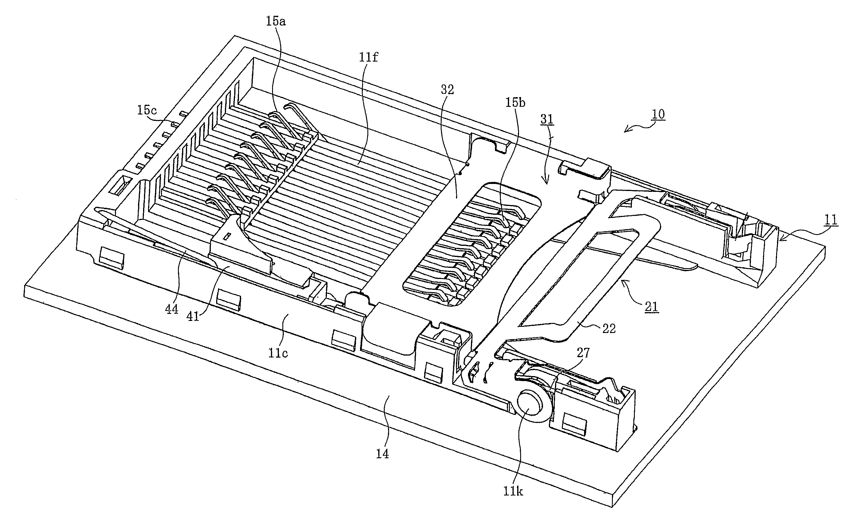
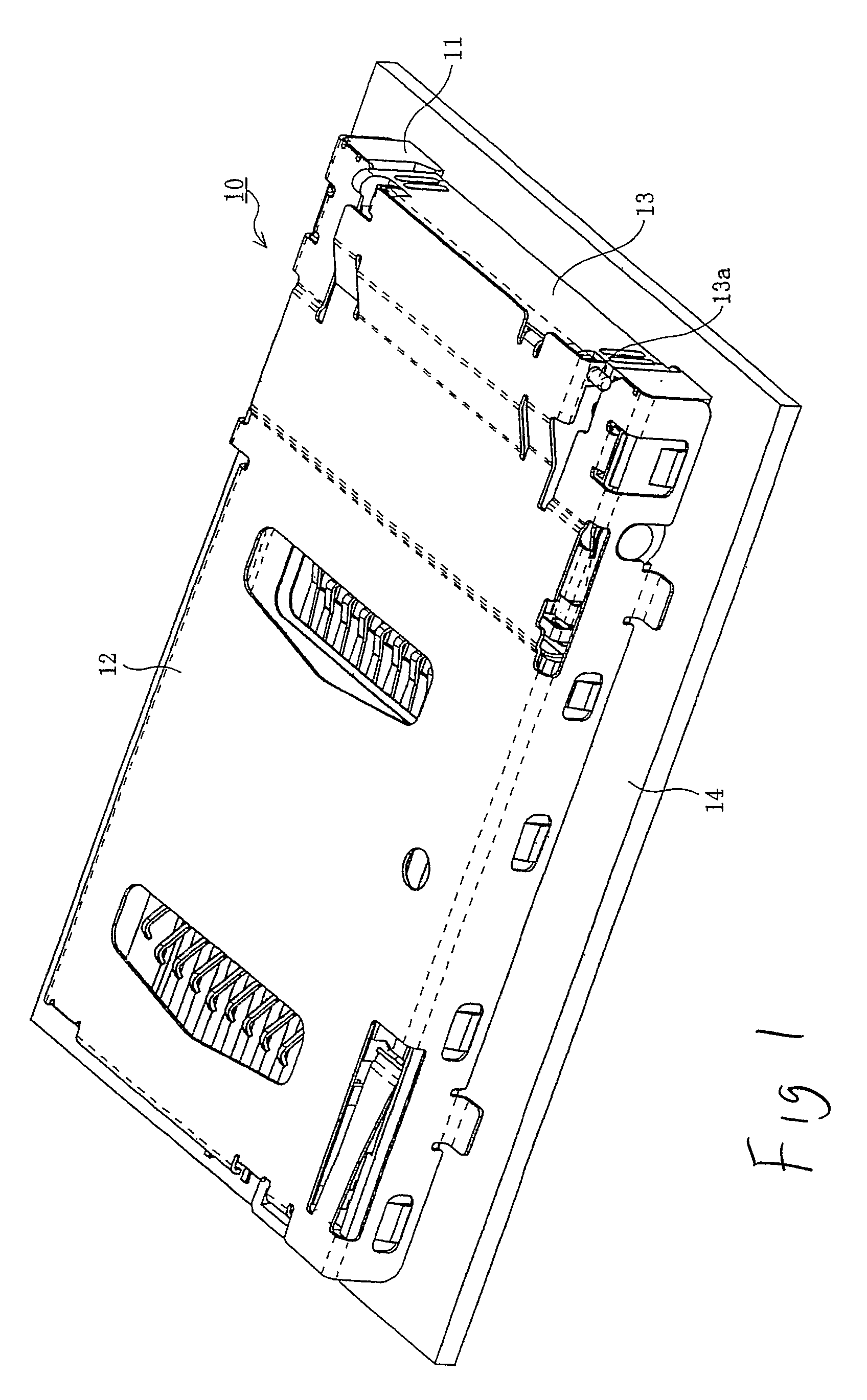
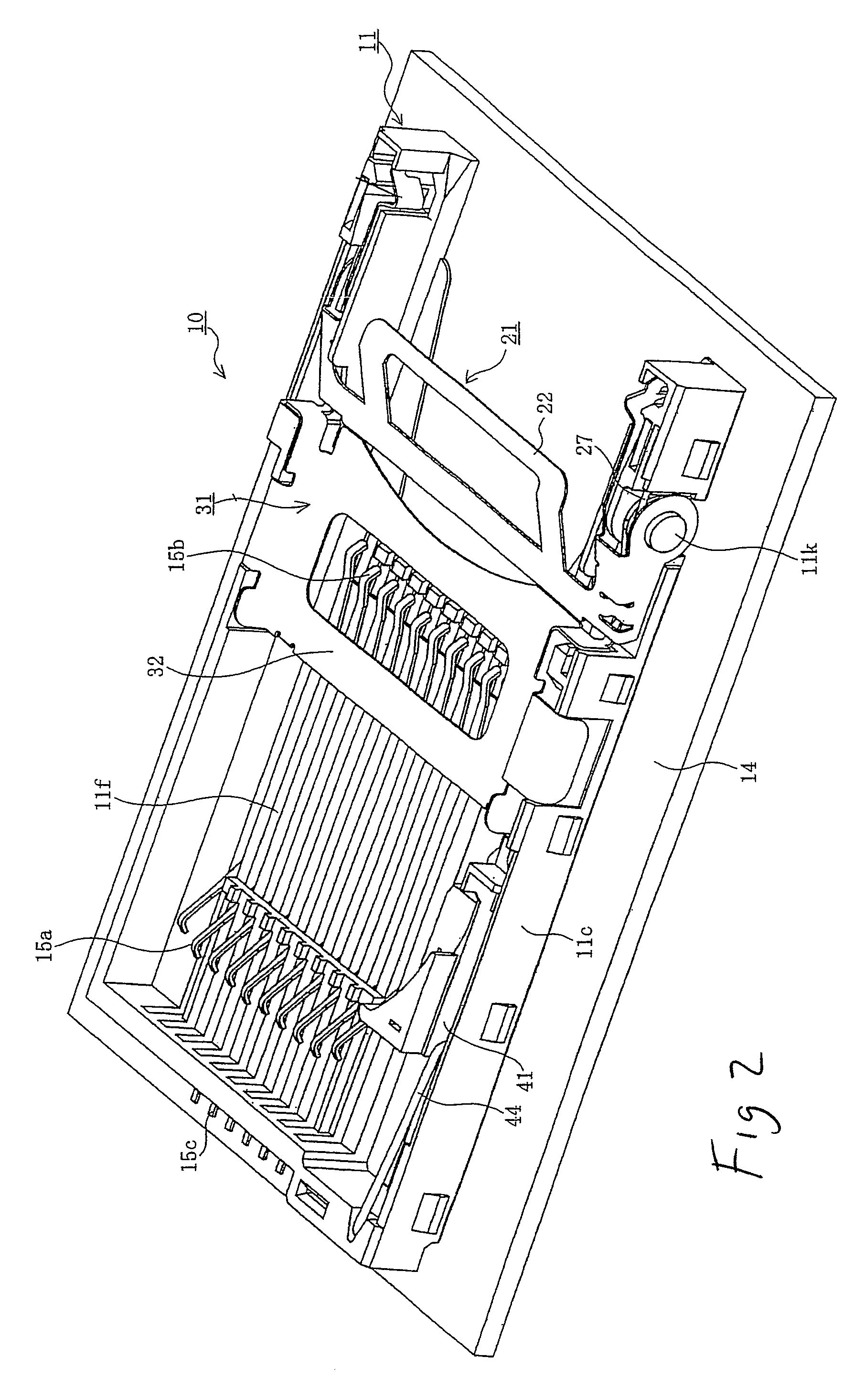
[0040]An embodiment of the present invention will next be described in detail with reference to the drawings.

[0041]In FIGS. 1 to 6, reference 10 denotes a card connector according to the present embodiment, which is mounted on a surface of a circuit board 14 attached to an unillustrated electronic device. One of a first card 51a and a second card 51b, which will be described later, is selectively loaded into the interior of the card connector 10, whereby the first card 51a or the second card 51b is attached to the electronic device via the card connector 10. The card connector 10 is of a so-called two-in-one type, and enables exclusive loading of the first card 51a or the second card 51b. The electronic device may be any type of device, such as a personal computer, a mobile telephone, a PDA, a digital camera, a video camera, a music player, a game machine, or a vehicle navigation device.

[0042]The first card 51a and the second card 51b may be any type of IC card; for example, an SIM ...


PUM


Abstract

A card connector (10) may receive first and second cards includes a housing (11) having an insertion opening for receiving cards (51a and 51b), a plurality of first connection terminals (15a) disposed in the housing and configured to engage pads of the first card (51a) and a plurality of second connection terminals (15b) disposed in said housing and configured to engage pads of the second card (51b). A guide member (21) is movably attached to the housing (11) at a position between the second connection terminals (15b) and the insertion opening and is adapted to engage an inserted card and direct the card to one of a first path and a second path to properly position the first and second cards upon insertion into the card connector.

Description

BACKGROUND OF THE INVENTION[0001]1. Field of the Invention[0002]The present invention relates generally to electrical connectors and more particularly to a card connector.[0003]2. Description of the Related Art[0004]Conventionally, electronic devices, such as personal computers, mobile telephones, personal digital assistants (PDAs), digital cameras, video cameras, music players, game machines, and vehicle navigation devices, include card connectors so as to enable use of various types of memory cards, such as subscriber identity module (SIM) cards, multi-media cards (MMCs), secure digital (SD) cards, mini SD cards, xD picture cards, memory sticks, memory sticks Duo, and smart media.[0005]With recent downsizing of electronic equipment, memory cards likewise tend to be rapidly reduced in size. Therefore, there has been proposed a so-called two-in-one type card connector which can receive not only a memory card of an ordinary size but also a memory card of a reduced size (see Japanese ...

Claims


Application Information

Patent Timeline
Patent Type & Authority Patents(United States)
IPC IPC(8): H01R24/00
CPCG06K7/0021G06K7/0043G06K13/08G06K13/0887G06K7/01H01R13/518H01R31/06
Inventor MATSUMOTO, YASUYOSHITOMITA, MITSUHIRO
Owner MOLEX INC
Why Eureka
Try Eureka