Intervertebral implant with movement resistant structure

a technology of intervertebral implants and movement resistance, which is applied in the field of implants, can solve the problems of gradual loosening of fasteners, ineffective structures designed to prevent relative movement between implants and engaged spinal elements, and failure of spinal fusion procedures, etc., and achieves the effects of facilitating fusion, increasing contact area, and enhancing spinal stability

Inactive Publication Date: 2010-11-16
WARSAW ORTHOPEDIC INC
View PDF54 Cites 137 Cited by
  • Summary
  • Abstract
  • Description
  • Claims
  • Application Information

AI Technical Summary

Benefits of technology

[0018]It is, therefore, an object of the present invention to provide an implant unit capable of supporting loads and, in a preferred embodiment, through its bone healing activity. Inherent in this activity, is the implant's ability to incorporate medically / surgically useful substances to a surgical site, promote and / or accelerate new bone growth.

Problems solved by technology

Structures designed to prevent relative movement between the implant and engaged spinal elements may not always be effective.
Thus, spinal fusion procedures may fail due to movement of the implant in relation to the adjoining vertebrae during the fusion process.
Such an uneven distribution of loads causes gradual loosening of the fasteners traversing the retaining portion that attach to the vertebrae.
But for the fasteners attaching the retaining part to the vertebrae, the retaining part does not have any additional load-bearing surface capable taking loads imposed on the spine.
As a consequence, known structures of retaining plates have limited contact areas between the implant and the bony mass of the spine.
A metallic implant always remains a foreign body, which is not able to accurately mimic the biomechanical or biological characteristics of the spine.
Although such a metallic implant often consists of an internal graft promoting incorporation and growth of new bone tissue as a result of its osteoconductive capabilities, metallic parts consisting of a cage and a retaining portion do not promote wound healing and / or remodeling of new bone.
A large part of the metallic implant never fuses with the adjoining bone and never is replaced by host bone and, thus, will never recover its original, natural qualities.
Furthermore, a subsequent surgery is often required to remove the retaining portion of the construct.
Since a large area between the metallic implant and the adjacent bone is not capable of fusion, relative motion between the bone and implant may cause gradual loosening of fasteners, which, in turn, leads to undesirable implant mobility.
Under certain circumstances such a phenomenon may lead to neural damage, vascular damage and / or bleeding.

Method used


Image

  • Intervertebral implant with movement resistant structure
  • Intervertebral implant with movement resistant structure
  • Intervertebral implant with movement resistant structure

Examples


Embodiment Construction

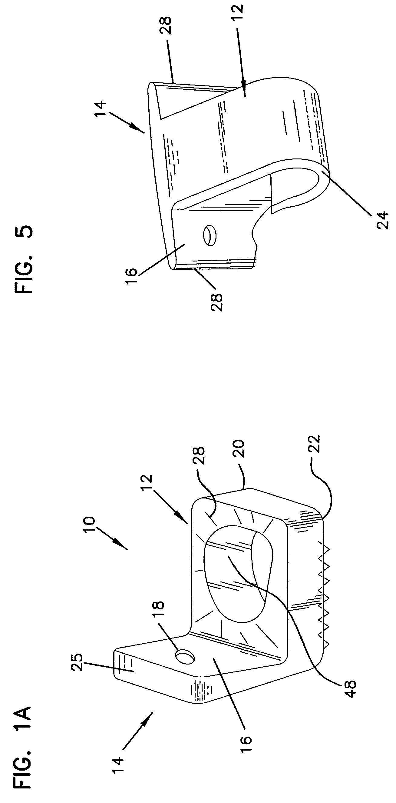
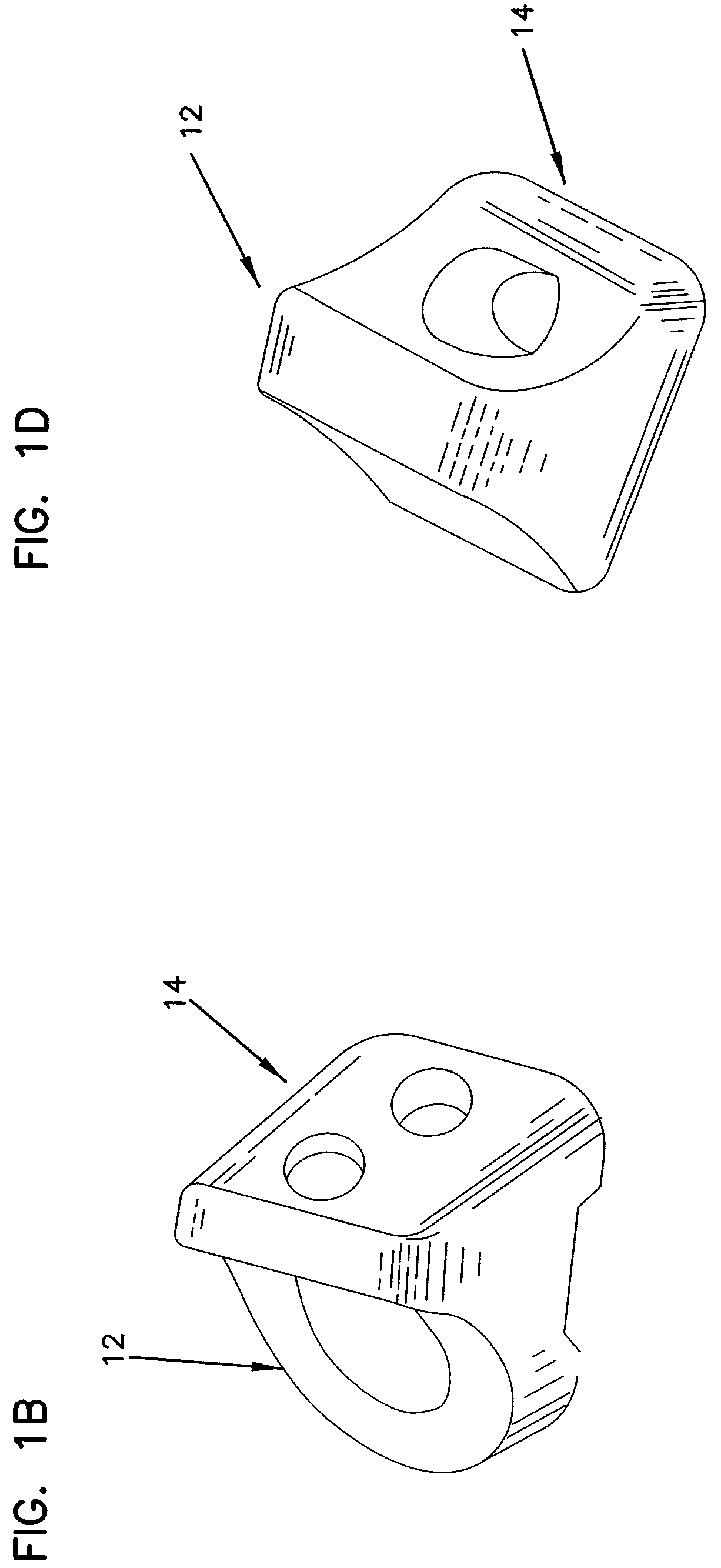
[0061]Preferred embodiments of the presently disclosed intervertebral implant unit with movement resistant structure will now be described in detail with reference to the drawings, in which like reference numerals designate identical or corresponding elements in each of the several views.

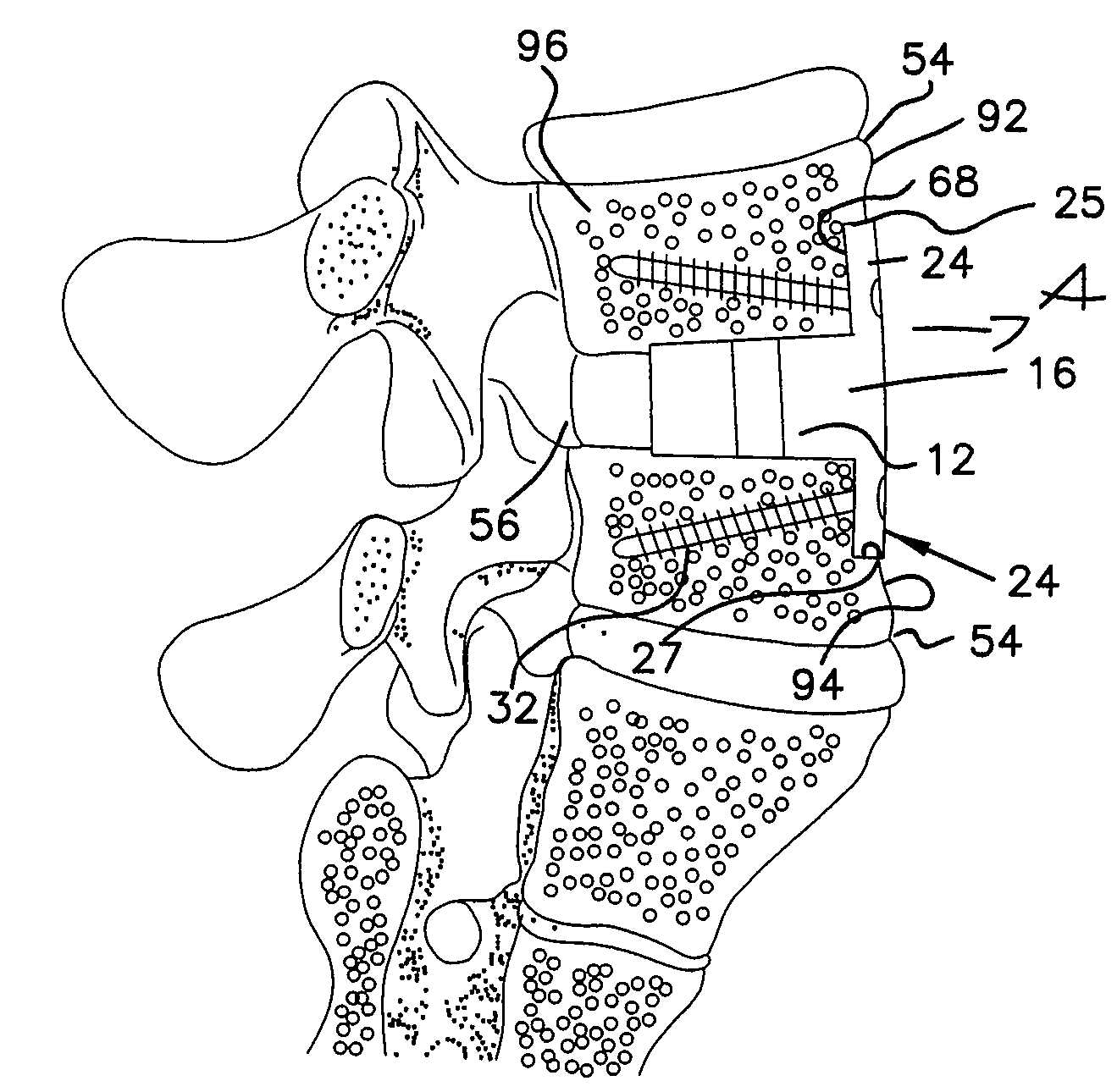
[0062]Referring to FIGS. 1A-1D, the inventive monolithic implant unit can have a variety of configurations adapted to provide new bone ingrowth and fusion of human or animal bones by one or more biological mechanisms. These mechanisms include chondrogenesis, osteogenesis, osteoconduction and / or osteoinduction that ultimately leads to complete fusion of the implant to adjoining bone structures. Although the following discussion is mostly concentrated on disclosing anterior and lateral cervical, thoracic, and lumber implants / instrumentation, the inventive concept can be easily adopted to a variety of surgical procedures providing immediate biomechanical stability to various bone structures and / or join...


PUM

PropertyMeasurementUnit
thickaaaaaaaaaa
displacementaaaaaaaaaa

Abstract

An implant unit used in surgery has a body made from osteogenic implantable material and including an implant portion and a retaining portion, which is coupled to and extends transversely to the implant portion. The retaining portion is attached to the sidewall of the adjoining vertebral body or mammal bone to prevent displacement of the implant portion relative to the vertebral body or mammal bone and to accelerate fusion therebetween.

Description

CROSS REFERENCE TO RELATED APPLICATION[0001]This application claims priority from Provisional Application Ser. No. 60 / 304,896 filed Jul. 12, 2001 and fully incorporated herein by reference.BACKGROUND[0002]1. Technical Field[0003]The present disclosure relates generally to an implant for insertion into a receiving bed formed between adjoining vertebrae. Particularly, the invention relates to an intervertebral implant adapted to fuse with the adjoining vertebrae and including a movement resistant structure for preventing relative motion between the intervertebral implant and the adjoining vertebrae during the period required for fusion.[0004]2. Background of Related Art[0005]Surgical implants are well known in the art for treatment of the spine for deficiencies including disease, trauma, deformity, and / or degenerative spinal conditions. The purpose of the implant is to reinforce and fuse with the spine by use of strategically placed attachment tools or implants. When a segment of the ...

Claims


Application Information

Patent Timeline
Patent Type & Authority Patents(United States)
IPC IPC(8): A61B17/70A61F2/44A61B17/86A61F2/00A61F2/02A61F2/28A61F2/30
CPCA61F2/28A61F2/4455A61B17/86A61F2/30965A61F2/446A61F2002/2839A61F2002/30057A61F2002/30059A61F2002/30062A61F2002/30131A61F2002/30176A61F2002/30354A61F2002/30405A61F2002/30492A61F2002/30578A61F2002/30677A61F2002/30777A61F2002/30785A61F2002/30836A61F2002/30841A61F2002/3085A61F2002/30904A61F2002/4475A61F2002/449A61F2210/0004A61F2220/0025A61F2220/0033A61F2230/0013A61F2230/0054A61F2310/00017A61F2310/00023A61F2310/00131A61F2310/00293A61F2310/00365A61F2002/30593
Inventor KAES, DAVID R.MORRIS, JOHN W.SHIMP, LAWRENCE A.WINTERBOTTOM, JOHNGEISLER, FRED
Owner WARSAW ORTHOPEDIC INC
Why Eureka
Try Eureka