Water detection and 3-phase fraction measurement systems

a technology of water detection and fraction measurement, applied in the field of flow analysis, can solve the problems of changing flow area, affecting the flow rate of gas wells, and causing unsafe flow conditions,

Active Publication Date: 2010-11-16
WEATHERFORD TECH HLDG LLC
View PDF18 Cites 17 Cited by
  • Summary
  • Abstract
  • Description
  • Claims
  • Application Information

AI Technical Summary

Benefits of technology

[0009]Methods and apparatus generally relate to monitoring a hydrocarbon well for water within a flow stream of the well. A water detector includes a light source for emitting into a flow stream infrared light that includes a water absorbent wavelength band. A detector measures the transmitted light of the water absorbent wavelength band passing through at least a portion of the flow stream. The water detector outputs a presence of water and / or a phase fraction or quantification of water as determined based on the attenuation. Measuring attenuation of a substantially transmissive wavelength band with respect to water simultaneously with measurement of the attenuation of the water absorbent wavelength band can enable correction for non-wavelength dependent attenuation. Some embodiments may include a hydrocarbon absorbent wavelength band and / or, in some instances, a second water absorbent peak that can differentiate water from alcohols.

Problems solved by technology

However, known measurement techniques suffer from their own unique drawbacks and / or limitations.
Onset of water in gas wells and wet gas wells introduces the prospect of ice-like hydrate formation, which can plug lines and create unsafe flowing conditions.
Furthermore, gas wells that are often high rate produce large pressure drops across chokes and flow area changes.
At these locations, Joule Thompson cooling can reduce temperatures significantly which may result in severe hydrate problems in a matter of hours or even minutes if water is present.
Serious problems result once the hydrates form and block or limit flow.
However, cleaning and treatment procedures required at surface to remove the hydrate inhibitor along with high costs of the inhibitor itself contribute to production expenses.
Therefore, injection of methanol as an exemplary hydrate inhibitor unnecessarily increases costs when preformed even if water is not present or when done at levels beyond that required based on the water that is present.

Method used


Image

  • Water detection and 3-phase fraction measurement systems
  • Water detection and 3-phase fraction measurement systems
  • Water detection and 3-phase fraction measurement systems

Examples


Embodiment Construction

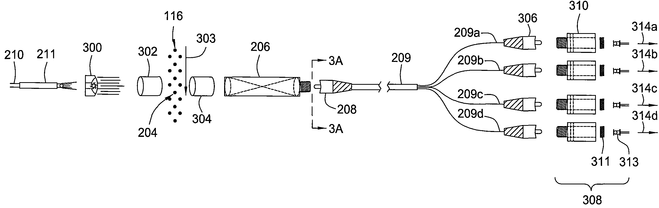
[0019]Embodiments of the invention generally relate to water detectors that utilize infrared optical analysis techniques. While the water detector is illustrated herein as part of a test system that is also capable of detecting phase fractions from a flow stream being produced from a well, use of the water detector includes various other applications and can provide moisture detection without requiring water quantification or such further phase fraction detection. For example, other industries such as pharmaceutical, food, refinery, chemical, paper, pulp, petroleum, gas, mining, minerals and other fluid processing plants often utilize flow assurance systems in order to detect whether or not water is present at all.

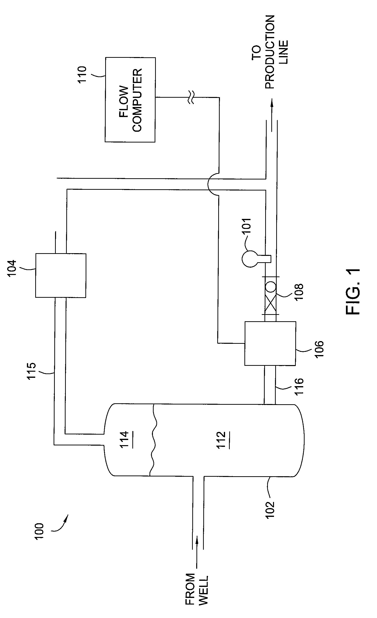
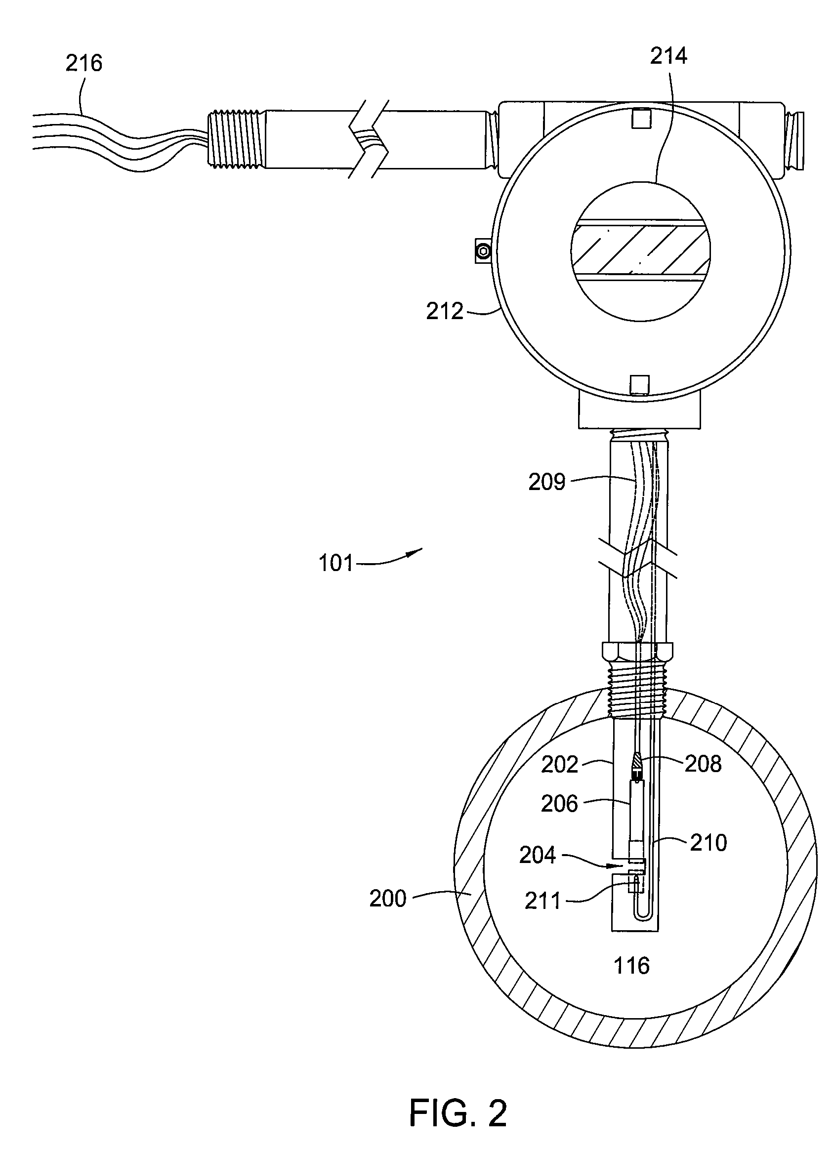
[0020]FIG. 1 shows a well testing system 100 including an infrared phase fraction meter 101 in accordance with embodiments of the invention. U.S. Pat. Nos. 6,076,049 and 6,292,756, which are herein incorporated in their entirety, further describe examples of infrared water...


PUM


Abstract

Methods and apparatus enable monitoring a hydrocarbon well for water within a flow stream of the well. A water detector includes a light source for emitting into a flow stream infrared light that includes a water absorbent wavelength band. A detector detects attenuation of the water absorbent wavelength band upon the infrared radiation passing through at least a portion of the flow stream. The water detector outputs a presence of water and / or a phase fraction or quantification of water as determined based on the attenuation. Detecting attenuation of a substantially transmissive wavelength band with respect to water simultaneously with detection of the attenuation of the water absorbent wavelength band can enable correction for non-wavelength dependent attenuation.

Description

CROSS-REFERENCE TO RELATED APPLICATIONS[0001]This application is a continuation-in-part of U.S. patent application Ser. No. 11 / 065,489, filed Feb. 24, 2005, now U.S. Pat. No. 7,233,001 which is herein incorporated by reference.BACKGROUND OF THE INVENTION[0002]1. Field of the Invention[0003]Embodiments of the invention generally relate to flow analysis.[0004]2. Description of the Related Art[0005]Oil and / or gas operators periodically measure water / oil / gas phase fractions of an overall production flow stream in order to aid in improving well production, allocating royalties, properly inhibiting corrosion based on the amount of water and generally determining the well's performance. Various approaches for analyzing the phase fraction of such flow streams exist and include full or partial phase separation and sensors based on capacitive, density and microwave measurements. However, known measurement techniques suffer from their own unique drawbacks and / or limitations.[0006]Wells often p...

Claims


Application Information

Patent Timeline
Patent Type & Authority Patents(United States)
IPC IPC(8): G01V5/08
CPCG01F1/74G01N21/314G01N21/3554G01N21/8507G01N33/2847G01N2021/3137G01N2021/3166G01N2021/3177G01N2021/3188G01N21/31G01N21/35G01N21/85G01N33/28
Inventor LIEVOIS, JOHNJOHANSEN, ESPEN S.ADEJUYIGBE, BABAJIDE
Owner WEATHERFORD TECH HLDG LLC
Why Eureka
Try Eureka