
Methods and systems for managing variable delays in packet transmission

a packet transmission and variable delay technology, applied in the field of methods and systems for managing variable delay in packet transmission, can solve problems such as mechanical or electrical changes, packet arrival times vary, and poor playout quality

Inactive Publication Date: 2010-11-16
QUARTICS
View PDF113 Cites 50 Cited by
  • Summary
  • Abstract
  • Description
  • Claims
  • Application Information

AI Technical Summary

Benefits of technology

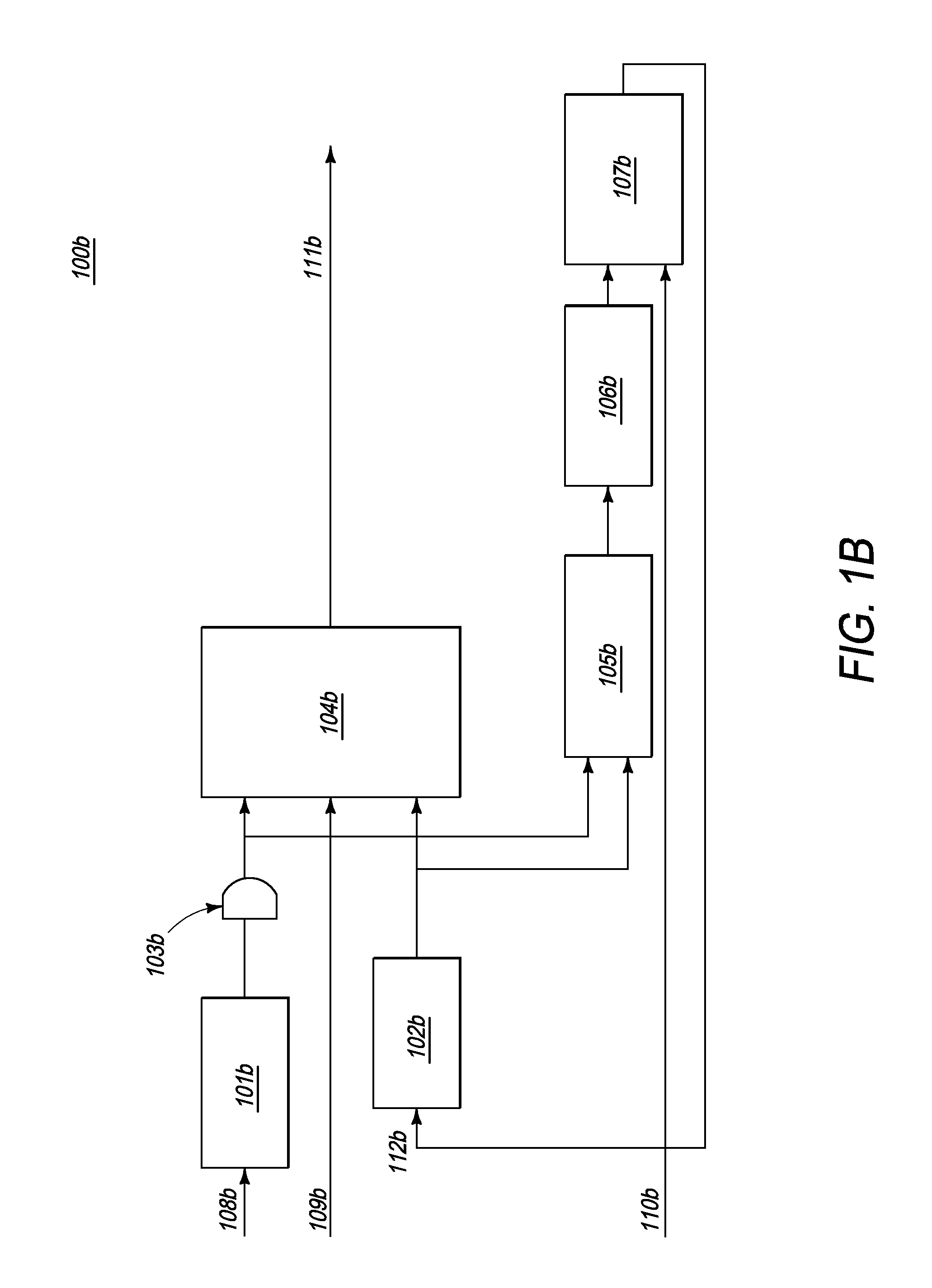
"The present invention provides better methods and systems for creating jitter buffers. These buffers can capture a large number of packets without being resource-intensive. The invention uses a packet delay histogram to determine the buffer size and delay, which is then used to select, store, and output packets at their adjusted playout time. This invention can be used in media gateways that manage jitter and provide media processing functions for data communications among heterogeneous networks."

Problems solved by technology

Jitter is the variable delay experienced in the course of packet transmission, resulting in varied packet arrival times, and is caused by networks providing different waiting times for different packets or cells.
It may also be caused by lack of synchronization, which results from mechanical or electrical changes.
If the buffer delay or length is too short, “slower” packets will not arrive before their designated playout time and playout quality suffers.
If the buffer delay is very long, it conspicuously disrupts interactive communications.
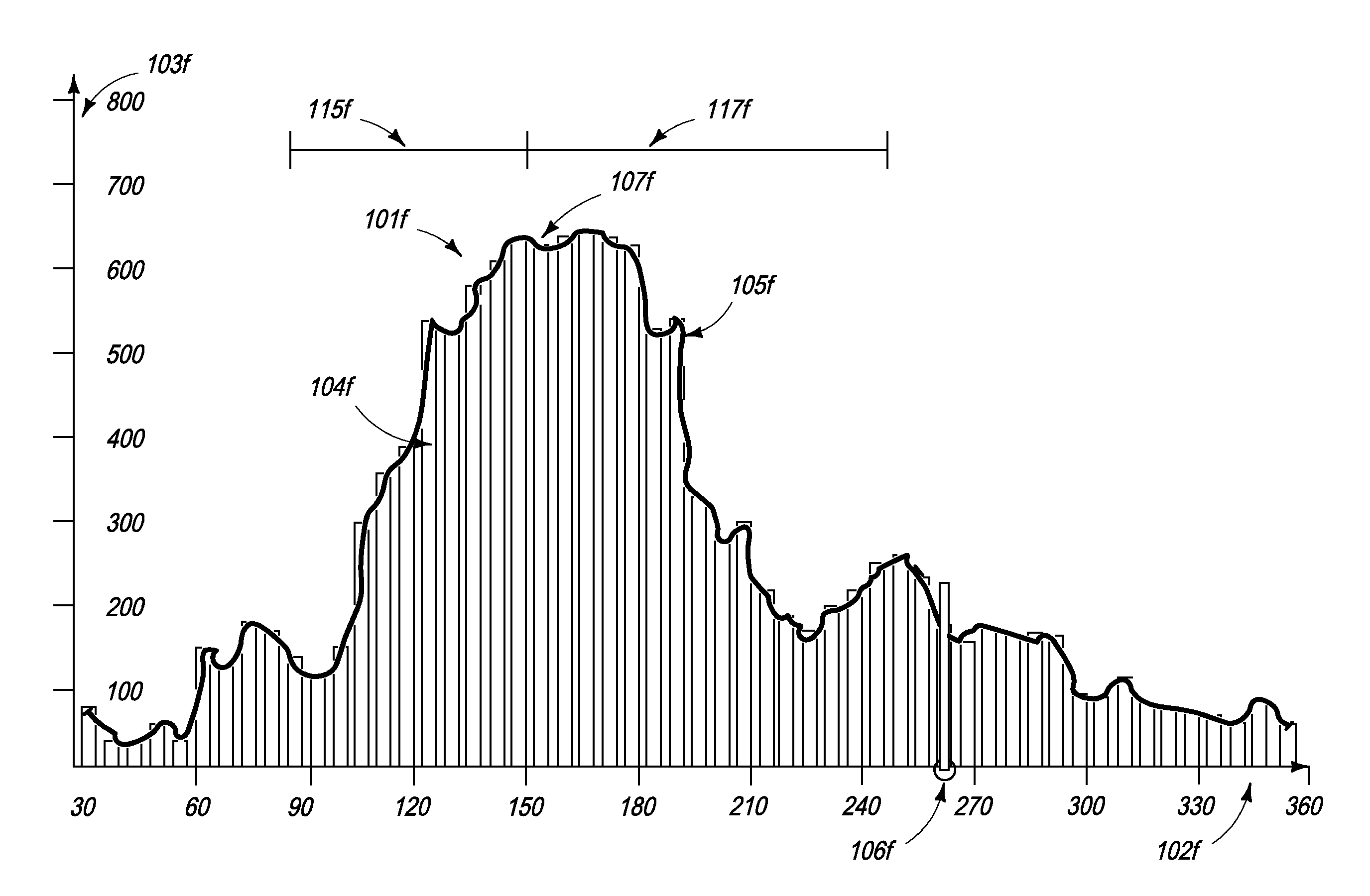
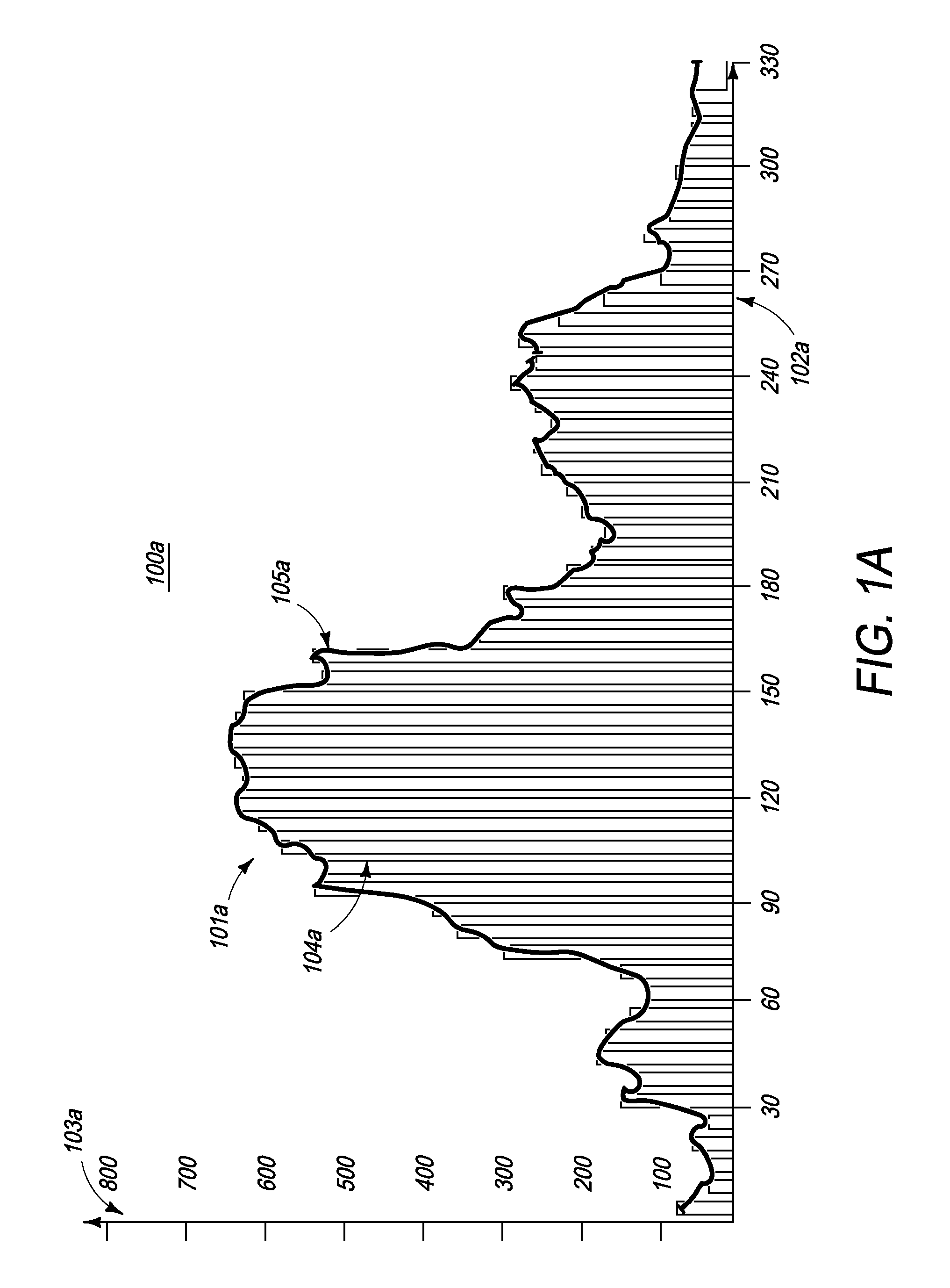
Typically, in telecommunications applications, PDD curves are often skewed earlier in time due to less delay experienced by most of the packets and, therefore, are often not symmetrical around the peak.

Method used


Image

  • Methods and systems for managing variable delays in packet transmission
  • Methods and systems for managing variable delays in packet transmission
  • Methods and systems for managing variable delays in packet transmission

Examples


first embodiment

[0101]Referring to FIG. 2a, the top-level hardware system architecture is shown. A data bus 205a is connected to interfaces 210a existent on a first novel Media Engine Type I 215a and on a second novel Media Engine Type I 220a. The first novel Media Engine Type I 215a and second novel Media Engine Type I 220a are connected through a second set of communication buses 225a to a novel Packet Engine 230a which, in turn, is connected through interfaces 235a to outputs 240a, 245a. Preferably, each of the Media Engines Type I 215a, 220a is in communication with a SRAM 246a and SDRAM 247a.

[0102]It is preferred that the data bus 205a be a time-division multiplex (TDM) bus. A TDM bus is a pathway for the transmission of a number of separate voice, fax, modem, video, and / or other data signals simultaneously over a single communication medium. The separate signals are transmitted by interleaving a portion of each signal with each other, thereby enabling one communications channel to handle mul...

second embodiment

[0175]The tone signaling component 1919, including recognition of DTMF / MF, call progress, call waiting, and caller identification, operates to intercept tones meant to signal a particular activity or event, such as the conducting of two-stage dialing (in the case of DTMF tones), the retrieval of voice-mail, and the reception of an incoming call (in the case of call waiting), and communicate the nature of that activity or event in an intelligent manner to a receiving device, thereby avoiding the encoding of that tone signal as another element in a voice stream. In one embodiment, the tone-signaling component 1919 is capable of recognizing a plurality of tones and, therefore, when one tone is received, send a plurality of RTP packets that identify the tone, together with other indicators, such as length of the tone. By carrying the occurrence of an identified tone, the RTP packets convey the event associated with the tone to a receiving unit. In a second embodiment, the tone-signaling...


PUM


Abstract

An improved method and system for the determination of jitter buffers enables the generation of buffers having sizes and delays such that, as designed, the buffers capture a substantial majority of packets while not being resource intensive. The present methods and systems provide for improved jitter buffer management by deriving playout buffer adjustments from a plurality of variances, centered around a distribution peak, or mean average delay. The playout buffer monitor uses the buffer adjustments, in size and delay, to select, store and playout packets at their adjusted playout time. The present invention may be employed in a media gateway that enables data communications among heterogenous networks and may be specifically deployed to manage jitter experienced in the course of receiving packetized data and processing the data for further transmission through a packet-based or circuit-switched network.

Description

RELATED APPLICATION DATA[0001]This is a continuation of U.S. patent application Ser. No. 10 / 084,559, filed on Feb. 25, 2002 now abandoned, which is a continuation-in-part of patent application Ser. No. 10 / 004,753, for DISTRIBUTED PROCESSING ARCHITECTURE WITH SCALABLE PROCESSING LAYERS, filed Dec. 3, 2001 now abandoned.FIELD OF THE INVENTION[0002]The present invention relates generally to a method and system for the communication of digital signals, and more particularly to a method and system for managing delays in packet transmission, e.g. managing jitter, using a buffering procedure, and to a media gateway deploying the jitter management methods and systems.BACKGROUND OF THE INVENTION[0003]Media communication devices comprise hardware and software systems that utilize interdependent processes to enable the processing and transmission of analog and digital signals substantially seamlessly across and between circuit switched and packet switched networks. As an example, a voice over ...

Claims


Application Information

Patent Timeline
Patent Type & Authority Patents(United States)
IPC IPC(8): G08C15/00G01R31/08G06F9/00G06F9/48G06F11/00H04J1/16H04J3/14H04L1/00H04L12/26
CPCG06F15/7842H04J3/0632H04J3/0697H04J3/14H04J1/16G06F11/00H04L1/00
Inventor PANG, JON LAURENTUSMAN, MOHAMMADKHAN, SHOAB AHMADRAHMATULLAH, MUHAMMAD MOHSIN
Owner QUARTICS
Learn More