Telescopic gun sight windage correction system

a windage correction and telescopic technology, applied in the field of improved windage correction systems, can solve the problems of inadvertent sighting on the incorrect reticle, the method of zeroing the rifle requires considerable time and the costly firing of bullets, and the stokey device, which is quite expensive and complicated, so as to achieve quick and accurate determination

Active Publication Date: 2010-11-23
SALVO TECH INC
View PDF16 Cites 50 Cited by
  • Summary
  • Abstract
  • Description
  • Claims
  • Application Information

AI Technical Summary

Benefits of technology

[0020]The present invention as thus described provides substantial advantages over those windage correction devices and systems found in the prior art. For example, the windage scale allows a user to quickly and accurately determine the appropriate windage correction value which should be used for the shot. Moreover, this is done without requiring the user to undertake extensive calculations to determine the appropriate windage correction, as the present scale generally eliminates the necessity for such calculations. Finally, although minute of angle windage correction scales have been used for a long time in connection with telescopic gun sights, use of such MOA scales still require substantial calculations to enable them to be used for windage correction, whereas the present invention requires almost no detailed calculations prior to use of the scale. It is therefore seen that the present invention provides a substantial improvement over those methods, systems and devices found in the prior art.

Problems solved by technology

Such a method of zeroing a rifle requires considerable time and the costly firing of bullets.
The Stokey device, however, was quite expensive and complicated.
Also, because the hunter always views two reticules within his field of vision through the scope, it was quite possible that the hunter would inadvertently sight on the incorrect reticle.
Also, the reticule which was sited in on target, could be off center from the field of vision through the scope causing further confusion and irritation to the hunter.
While the Stokey scope of 1937 suggested one-shot sighting, the inherent disadvantages, expense and complication of the system voided its general use.
Such magnification of the cross-hair wires is annoying to the hunter, blocking portions of his view.
Besides the problem of multiple firings to sight-in present day scopes, a problem of parallax exists when using the scope to shoot at close range.
Further problems with such conventional scopes include the addition of devices which serve to approximate range and determine the “hold over” or aiming point in view of the range of the target.
All of these range finding devices, however, add clutter to the hunter's field of vision and are particularly annoying when the hunter is shooting at close range and thus not using the range finding devices.
However, despite the various types of range finding indicia used with scopes of the prior art, there has been precious little development or improvement in the methods and devices available to hunters and shooters to correct for wind, and as wind correction is at least as critical to a successful shot as finding the range to the target, there is a need for significant improvement in this area.
It should be noted, however, that one additional concern with the Marine formula is that it is only accurate at 500 yards or less.
To perform all these calculations immediately prior to taking the shot is a difficult task to say the least, and therefore there is a need to improve and streamline the task of determining appropriate windage corrections.

Method used


Image

  • Telescopic gun sight windage correction system
  • Telescopic gun sight windage correction system
  • Telescopic gun sight windage correction system

Examples


Embodiment Construction

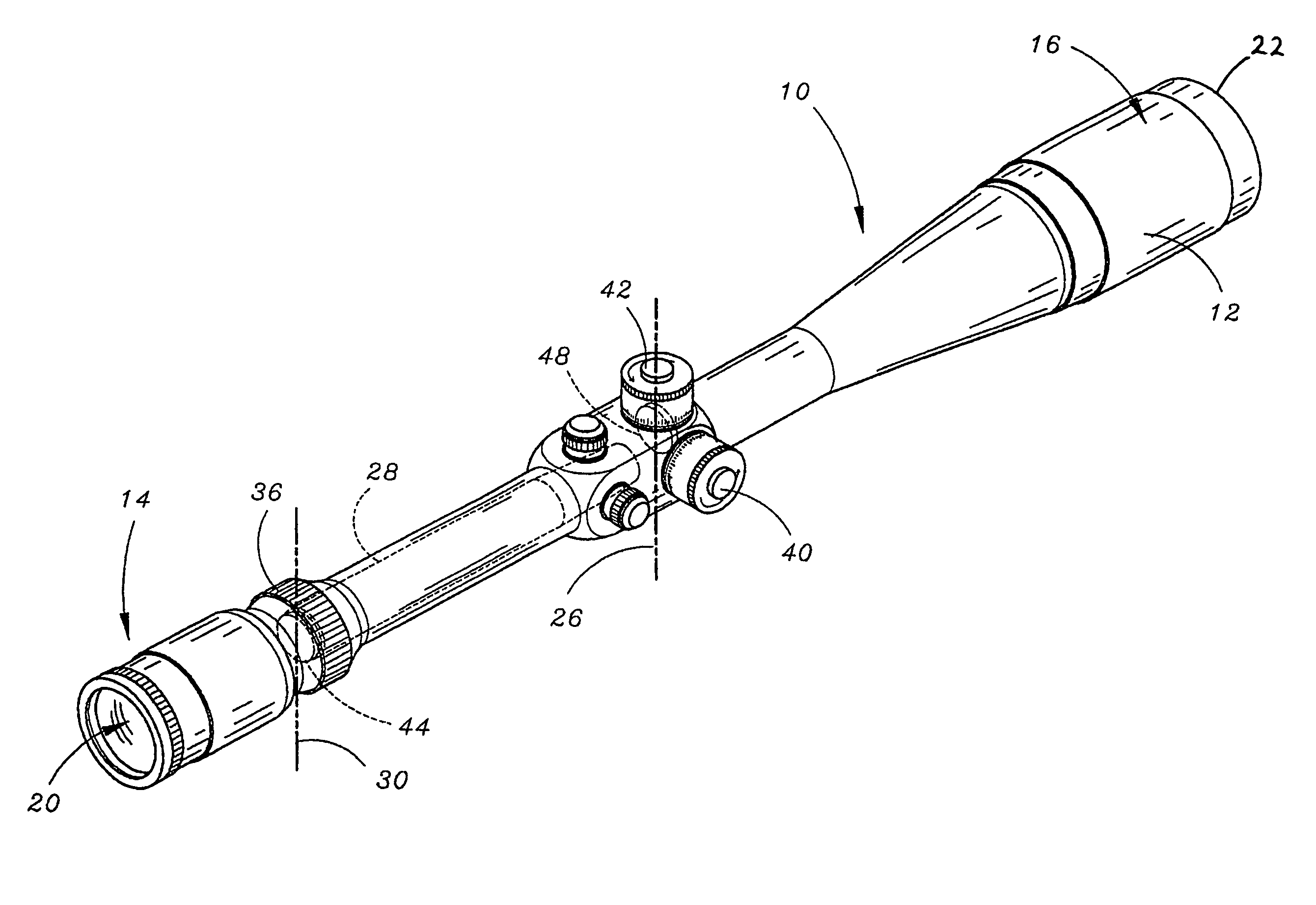
[0026]Referring to FIG. 1, the improved telescopic gun sight 10 is shown as including a pair of reticule adjustment knobs 40 and 42 disposed along the outside of the tubular housing 12 of the scope 10, for permitting the hunter to selectively adjust the effective position of a pair of sighting reticules disposed within the scope 10, in order to properly sight-in the rifle and correct for bullet drop and any crosswind.

[0027]The scope includes an eyepiece end 14 comprising an ocular lens system 20 through which the hunter views during siting of a target upon which he wishes to fire. The other end of the scope is the objective end 16 and includes an objective lens 22 which is directed toward the object to be viewed. The light rays coming from the object pass through objective lens 22 and converge to form an image on an image plane within the tubular housing and generally defined by reference numeral 26. Because the image appearing in the image plane will be the inverted image of the vi...


PUM


Abstract

An improved telescopic gun sight includes a telescopic gun sight at least including an adjustable lens configuration for adjustably magnifying an external object to form an object image, an inverting tube for inverting the object image, an ocular lens array for presenting the object image for viewing, a primary reticule including sighting insignia imprinted thereon and a secondary reticule being movable both horizontally and vertically in the image plane. The secondary reticule includes a generally horizontal windage correction scale operative to provide instant windage correction target alignment. It includes instant windage correction target alignment values positioned at point-specific spaced-apart locations with specific instant windage correction target alignment values corresponding to selected distance amounts calculated for a selected bullet type and weight.

Description

BACKGROUND OF THE INVENTION[0001]1. Technical Field[0002]The present invention relates to improvements in telescopic gun sights and, more particularly, to an improved windage correction system for a telescopic gun sight which includes a generally horizontal windage correction scale operative to provide instant windage correction target alignment and including instant windage correction target alignment values positioned at point-specific spaced-apart locations on the generally horizontal scale with specific instant windage correction target alignment values corresponding to selected distance amounts calculated for a selected bullet type and weight.[0003]2. Description of the Prior Art[0004]Present telescopic sites used on rifles and other firearms, generally comprise a cross-hair reticule positioned within the scope for referencing the hunter's vision with respect to a target. A hunter “sights in” or “zeros” the scope by firing bullets in a trial-by-error method and repetitively adj...

Claims


Application Information

Patent Timeline
Patent Type & Authority Patents(United States)
IPC IPC(8): F41G1/38
CPCF41G1/44
Inventor SHEPHERD, DANIEL R.
Owner SALVO TECH INC
Why Eureka
Try Eureka