Water heater with condensing flue

a water heater and condensing flue technology, applied in water heaters, furnace-tube steam boilers, climate sustainability, etc., can solve the problem of wasting more time between heat transfer, and achieve the effect of easy adjustment of heat transfer in the vertical flue and less resistance to gas flow

Active Publication Date: 2010-11-23
BOCK WATER HEATERS
View PDF28 Cites 13 Cited by
  • Summary
  • Abstract
  • Description
  • Claims
  • Application Information

AI Technical Summary

Benefits of technology

[0008]It is a further object of the present invention to provide a water heater with a condensing flue with lower resistance to gas flow.
[0009]It is another object of the present invention to provide a water heater wherein the heat transfer in the vertical flue can readily be adjusted by the number and placement of fins in the central flue.

Problems solved by technology

First, the baffles slow the passage of the combustion gases through the flue, giving more time for heat transfer between the gases and the flue wall.
Second, the baffles mix the combustion gases within the flue, bringing more of the flue gases into contact with the flue wall which transfers heat to the water.
Third, the baffles conduct heat to the wall of the flue.

Method used


Image

  • Water heater with condensing flue
  • Water heater with condensing flue

Examples


Embodiment Construction

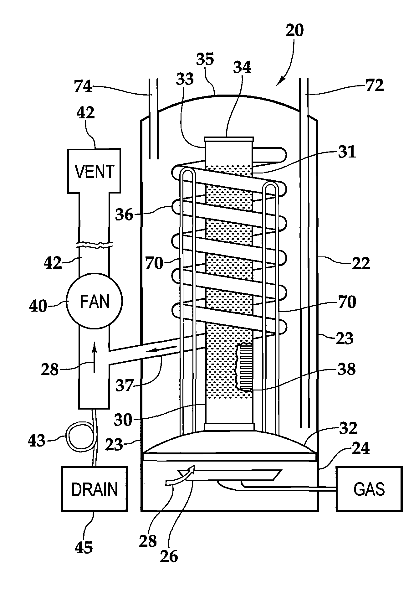
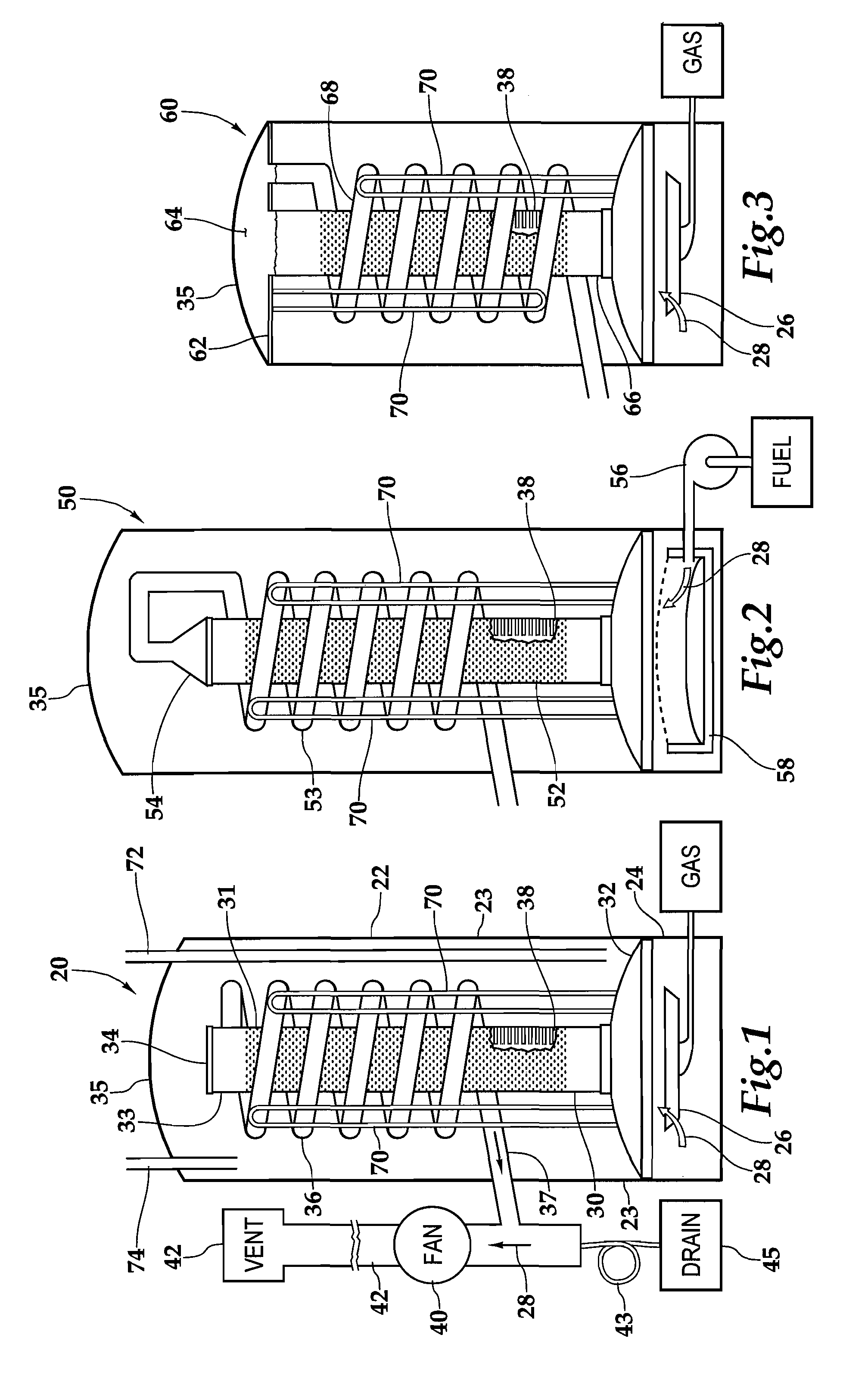
[0015]Referring more particularly to FIGS. 1-3 wherein like numbers refer to similar parts, a water heater 20 is shown in FIG. 1. The water heater 20 has a water tank 22 with an outer cylindrical wall 23. The water heater 20 has a combustion chamber 24 positioned below the water tank 22 which contains an atmospheric gas burner 26. The burner 26 supplies combustion gases indicated by arrows 28 to a straight central cylindrical flue 30 which extends upwardly from a convex dome 32 forming the bottom of the water tank 22. The central cylindrical flue 30 has a cylindrical wall 31. The central flue 30 terminates at a cap 34 beneath the upper convex dome 35 of the water heater tank 22. A condensing flue 36 is joined to the central flue 30 at a penetration formed in the central flue cylindrical wall 31 at an upper portion 33 of the central flue 30. The combustion gases flow into the condensing flue 36 which extends helically downwardly in the water tank 22 terminating in a strait section 37...


PUM


Abstract

A water heater has a burner positioned below a vertical centrally located flue with heat exchange capacity enhanced by a multiplicity of rectangular metal fins which are welded on the inside of the vertical central flue. The central flue extends upwardly within a water tank. The central flue transitions to a smaller diameter downwardly draining helically coiled condensing flue. Approximately 80% of the heat from the combustion gases is transferred to the water within the water tank through the wall of the central flue without condensation. An additional 10% or more of the combustion heat is transferred to the water accompanied by condensation of water in the coiled flue. A fan draws the combustion gases through the central flue and the coiled condensing flue and supplies the combustion gases to an exterior vent.

Description

BACKGROUND OF THE INVENTION[0001]The present invention relates to water heaters in general and to bottom fired central flue water heaters with internal heat exchange structures in particular.[0002]Heat exchange between a liquid and a gas is a process which has many industrial and domestic applications. Perhaps one of the most widely used applications of heat exchange between a gas and a liquid is in heating hot water. Typically a hot water heater has a tank which holds the water to be heated, and a burner producing hot combustion gases. The water is heated by the combustion of fuel with air in the burner to produce combustion gases which heat the bottom of the tank and are vented through a centrally located flue / heat exchanger which extends through the hot water tank. Two considerations which are paramount in the design of a hot water heater are durability and efficiency. Ever since the early 1970s there has been a heightened awareness of the importance of efficiency for cost, envir...

Claims


Application Information

Patent Timeline
Patent Type & Authority Patents(United States)
IPC IPC(8): F24H1/52
CPCF24H1/206F24H8/00Y02B30/102Y02B30/00
Inventor MULLEN, TERRENCE J.STEINHAFEL, MICHAEL B.
Owner BOCK WATER HEATERS
Why Eureka
Try Eureka